
LM4911 without an output capacitor OCL power circuit

The LM4911 is a low-power audio amplifier designed for applications requiring high efficiency and minimal component count. In configurations without an output capacitor, the circuit can achieve a more compact design, reducing the overall footprint of the system. The absence of an output capacitor in the power circuit allows for a direct connection between the amplifier output and the load, which can be advantageous in achieving better transient response and lower distortion.
The shutdown control (SD) feature is critical in this configuration, as it ensures that the amplifier can quickly turn off in response to control signals, thereby preventing any unwanted audible artifacts such as bashing noise during transitions. This rapid response is particularly useful in battery-operated devices, where power conservation is essential. The squelch control (Mute) is typically used to suppress noise during idle periods; however, in this design, the shutdown control serves as a more effective solution, providing a cleaner output without the need for additional components.
The power consumption of the circuit is an important factor to consider, especially in low-power applications. The maximum power consumption is calculated using the formula PDMAX = 4VDD² / (2R), where VDD represents the supply voltage and R is the load resistance. This equation highlights the relationship between supply voltage, load resistance, and power dissipation, which is crucial for designing efficient audio amplification systems.
Overall, the LM4911's configuration without an output capacitor presents a viable solution for applications that prioritize compactness and efficiency while maintaining audio quality. The design effectively balances the need for rapid shutdown capabilities with the goal of minimizing power consumption and noise. As shown for the LM4911 no output capacitor (OCL) power circuit. Without an output capacitor (OCL) power circuit without using squelch control (Mute), because then the shutdown control (SD) faster than the squelch control (Mute) comes and turns off to eliminate the slightly - bashing noise. The maximum power consumption without an output capacitor circuit PDMAX 4VDD2/2R.
Related Circuits

This design outlines a door alarm circuit that utilizes an electronic system. It features a synthesized sound chip from Holtek, specifically the HT-2811, which reproduces the sound of a "ding-dong" chiming doorbell. The circuit also incorporates a CMOS 4026...
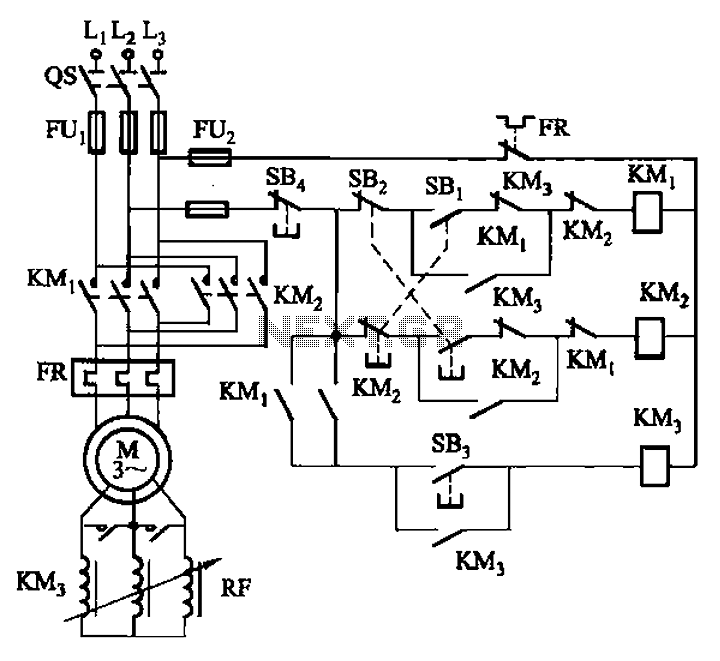
The circuit illustrated in Figure 3-166 employs a button control mechanism. To initiate forward motion, the user presses button SB1, which activates the motor rotor through a frequency-sensitive rheostat (RF). As the motor speed approaches its rated speed, a...
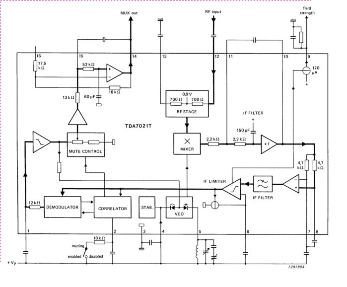
The TDA7021T integrated radio receiver circuit is designed for portable radios, both stereo and mono, where minimal peripheral components are essential for achieving small dimensions and low cost. It is fully compatible. The TDA7021T is a highly integrated radio receiver...
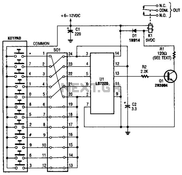
A block pinout diagram of the LS7220 keyless-lock IC is presented. The keypad must provide each key with a contact to a common connection. In this instance, the common connection is linked to the positive supply rail, allowing a...
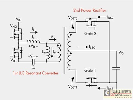
The designer is looking for a solution with higher efficiency and lower power consumption in order to minimize unnecessary energy loss. The approach involves using syntony inductance to harmonize the capacitive LLC syntony converter, employing zero voltage switching (ZVS)...
Signals with a known frequency but an unknown phase can be detected using an in-phase signal and a signal that is shifted by 90 degrees, a method commonly utilized in lock-in amplifiers, synchronous detectors, and frequency-response analyzers. The signal...