
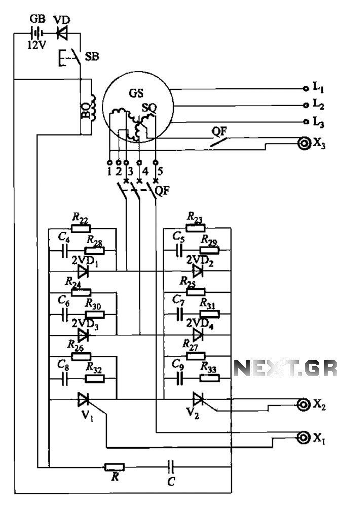
Frequency sensitive rheostat manually start reversing circuit

The circuit operates by utilizing a motor control system that integrates a frequency-sensitive rheostat to manage the motor's speed effectively. The button controls (SB1, SB2, and SB3) provide a user-friendly interface for initiating forward and reverse operations. When SB1 is pressed, it sends a signal to the motor control circuitry, allowing current to flow through the frequency-sensitive rheostat (RF). This component adjusts the voltage applied to the motor, thereby controlling its rotational speed based on the frequency of the input signal.
As the motor accelerates and approaches its rated speed, the user can short press button SB3, which triggers a feedback mechanism that momentarily disengages the RF. This allows the motor to run at its rated speed without the additional resistance from the rheostat, optimizing performance and efficiency.
For reverse operations, button SB2 is utilized to initiate the same process as the forward motion. The circuit design ensures that both forward and reverse operations can be performed smoothly, with the ability to adjust speed dynamically based on user input. The inclusion of frequency-sensitive control allows for precise speed management, making this circuit suitable for applications requiring variable motor control. Overall, this circuit exemplifies a practical approach to motor control using simple button interfaces and responsive electronic components. Circuit shown in Figure 3-166. It uses the button control. When start forward, press SB], the motor rotor string frequency sensitive people rheostat RF operation. When the moto r speed increased to close to the rated speed, short press the button SB3, RF out of operation. Reverse start, press SB2 to startup process forward and start the same process.
Related Circuits
The setup is connected to separate stator windings of a harmonic generator, which leads to a thyristor rectifier supply for the third harmonic voltage, positioned after the motor field. The output voltage varies with changes in the winding harmonics...
This high voltage converter circuit begins with a 30-volt power supply and is capable of delivering output voltages ranging from 0 to 3 kV for version 1, or from 0 to 10 kV for version 2. The high voltage converter...
The main circuit of the 6-channel mixer consists of six input channels. Channels 1-4 are mono, while channels 5-6 are designed for music use. The number of input channels can be increased as desired. The output of each channel...
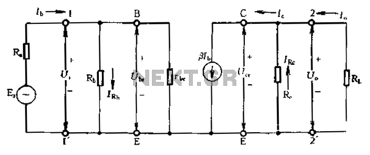
Calculate magnification, input resistance, and output resistance circuit. This circuit is designed to calculate the magnification, input resistance, and output resistance of a given electronic system. The magnification refers to the ratio of the output signal to the input signal,...
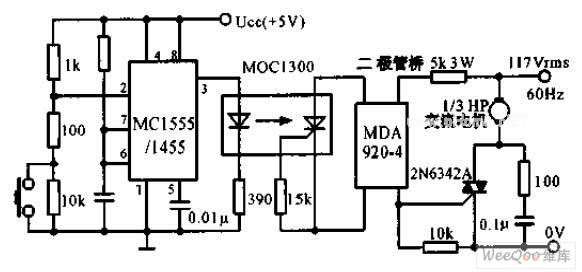
The switch shut-off time delay circuit consists of a timer, optocouplers, a bridge SCR, and an SCR AC switch. When the control button is released, it allows the motor or other AC power to remain active for one hour....
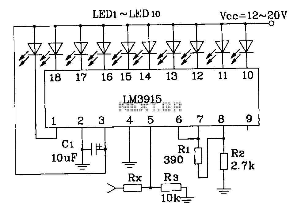
This document describes a simple LM3915 audio power meter circuit diagram. It notes that if the internal resistance of the speaker is 4 ohms, a resistor value of 10k ohms should be used for Rx. For an 8-ohm speaker,...