
Thermistor basic application circuit b

The basic thermistor application circuit serves as an essential tool for temperature measurement in various electronic systems. The circuit's design revolves around the thermistor's resistance change with temperature variations. In applications where precise temperature readings are not critical, such as in basic temperature sensing or environmental monitoring, the circuit provides a satisfactory solution.
In the first configuration (Figure a), the positive temperature coefficient thermistor (RT) operates by exhibiting a decrease in resistance as the temperature rises. This characteristic is leveraged to generate a corresponding increase in output voltage (vo), which can be monitored to ascertain temperature changes. This simple setup is straightforward but limited in its measurement accuracy, making it suitable for less demanding applications.
The second configuration (Figure b) incorporates a differential operational amplifier to enhance the accuracy of temperature measurements. This improvement is particularly useful in applications requiring the detection of temperature differentials between two thermistors (RT1 and RT2). The operational amplifier amplifies the voltage difference between the thermistors, allowing for more precise readings. When RT1 is cooler than RT2, the output reflects this difference, providing a low output voltage. This behavior reverses when RT2 is at a higher temperature, thus enabling the circuit to effectively measure and compare temperatures at different points.
The third configuration (Figure c) introduces a logarithmic diode, which helps linearize the response of the thermistor. This approach compensates for the non-linear characteristics of thermistors, allowing for a more accurate representation of temperature changes. The adjustable gain amplifier (rp) enables further customization of the circuit's response, allowing users to tailor the sensitivity and output range to meet specific application requirements.
Overall, these configurations illustrate the versatility of thermistors in temperature sensing applications, from basic circuits to more sophisticated designs that enhance measurement accuracy and adaptability. As shown for the basic application circuit thermistor. Figure (a) of the basic temperature measurement circuit. The circuit temperature measurement accuracy is not high, can on ly be used for less demanding precision applications. RT is a positive temperature coefficient thermistor, the temperature rises, the output voltage vo is increased, decreased and vice versa; RT negative temperature coefficient thermistor, the temperature rises, the output voltage vo is lowered, increased and vice versa. Figure (b) is measured using a thermistor temperature differential operational amplifier circuit, temperature measurement accuracy improved.
This circuit can detect a temperature difference between two points, which when RTi RT2 at a temperature lower than that RTi, operational amplifier (a) end potential is higher than (+) side potential, the output low; similarly, month in which temperature l rt2 when at high. fig il (c) use of an and logarithmic diode measurement circuit, thermistor linear compensate, rp adjustable gain amplifier, thereby further improving characteristics.
Related Circuits

Dew (condensed moisture) adversely affects the normal performance of sensitive electronic devices. A low-cost circuit described here can be used to switch off any gadget automatically in case of excessive humidity. At the heart of the circuit is an...
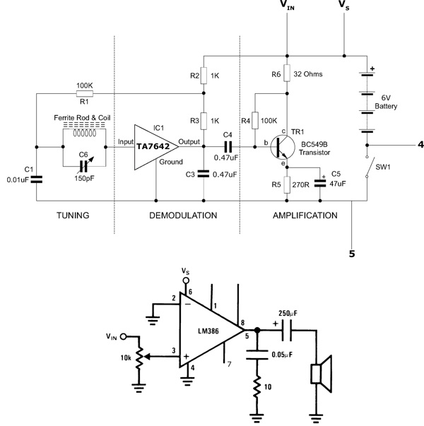
This functioning radio was built for an electronics module. The specified design was modified to include batteries, a switch, and a speaker instead of headphones. An additional amplifier circuit was required to power the speaker driver. Although not necessary,...
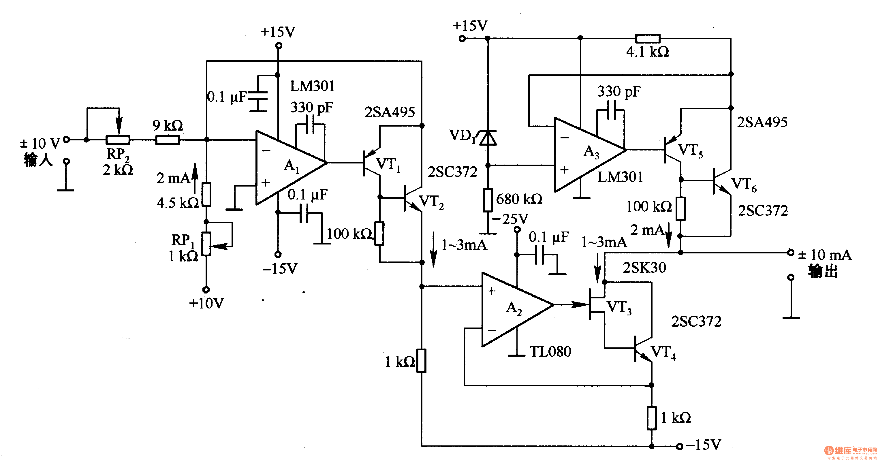
This circuit is designed for voltage-to-current conversion, specifically transforming a ±10V input voltage into a ±1mA output current. The conversion process is facilitated by operational amplifier A1 and transistors VT1 and VT2, which are responsible for altering the current...

This 555 timer circuit toggles a relay when a button is pressed. Pins 2 and 6, which are the threshold and trigger inputs, are maintained at half the supply voltage by two 10K resistors. When the output is high,...
The laser-pointer detection circuitry is capable of identifying when a laser light is directed at a specific photosensor. If the laser targets the top sensor, the comparator chip outputs a high signal. Conversely, if the laser is aimed at...

This source is selected by pressing a momentary-contact pushbutton switch (SI). Switch SI is connected to the trigger of a 555 oscillator/timer (U1) configured as a monostable multivibrator, which generates one short output pulse for each press of SI....