
Remote-Control Analyzer Circuit

The remote analyzer circuit provides a straightforward yet effective means of analyzing infrared signals. The power supply section begins with a transformer that converts the AC mains voltage to a lower AC voltage, suitable for the needs of the circuit. The 12.6-V transformer is connected to a bridge rectifier made up of four diodes (D1 to D4), which converts the AC voltage to pulsating DC. The capacitor (CI) smooths out the ripples in the rectified output, providing a more stable DC voltage to the subsequent components.
The 7805 voltage regulator (Ul) is a crucial component that ensures the output voltage remains at a constant 5 V, regardless of variations in input voltage or load conditions. This regulated voltage is essential for the proper functioning of the infrared detector module (MODI).
The GPIU52X infrared detector module is designed to demodulate signals at a frequency of 40 kHz, which is a common carrier frequency for infrared remote controls. This functionality allows the circuit to effectively capture and analyze infrared signals transmitted from remote control devices. The demodulated output, which consists of logic pulses representing the transmitted signal, is then routed to an oscilloscope through the BNC connector (PL2). This allows for visual analysis of the signal waveform, facilitating troubleshooting and verification of remote control operations.
LED1 serves as a visual indicator of the circuit's operational status, providing immediate feedback to the user when the circuit is powered on. The inclusion of the optional switch (SI) allows for convenient control of the circuit's power without the need to disconnect the power supply. Overall, this schematic diagram illustrates a well-designed circuit for analyzing infrared remote control signals, combining essential components for power regulation, signal demodulation, and user feedback. A schematic diagram for the remote analyzer is shown. The circuit is powered from a simple 5-V supply, consisting of PL1, SI, Tl, a bridge rectifier (comprised of D1 through D4), capacitor CI, and a common 5-V regulator, Ul. Switch SI is the on/off control and is optional. The power-supply transformer used in the prototype is a 12.6-Vac unit, but any transformer that can supply at least 5.6-Vac will do.
The 12.6-V unit was used solely because of its availability. The output of Tl is full-wave rectified by diodes D1 through D4 and filtered by CI. The bumpy dc output from the capacitor is regulated down to 5 V by Ul, a 7805 integrated regulator. LED1 acts as a power indicator to let you know that the circuit is active. The 5-Vdc powers a GPIU52X infrared-detector module* (MODI), which demodulates the 40-kHz carrier used by most infrared remotes. After demodulation, the resulting logic pulses are sent to an oscilloscope via PL2, a BNC connector.
Related Circuits
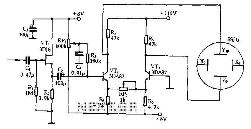
Application of the differential amplifier circuit in a simple small oscilloscope. The differential amplifier circuit is a crucial component in the design of a simple small oscilloscope. This circuit is designed to amplify the difference between two input voltage signals...

This circuit is designed for an LM1893 power line modem, which facilitates information transfer between remote locations using the power mains. The LM1893 serves as a power line interface for half-duplex (bi-directional) communication of serial bit streams employing various...
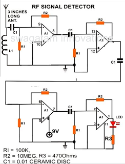
A simple electronic circuit project is presented that can be constructed by any school student for display at a school science fair. The proposed circuit is a high-gain operational amplifier (op-amp) amplifier designed to detect the slightest RF disturbances...
Two identical integrated circuits, U1 and U2, known as "hex inverters" are used for the theremin's primary functions. They are CMOS (Complimentary Symmetry Metal Oxide Semiconductor) devices, typically used in digital circuits to perform a logic function called "inversion."...
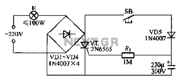
This circuit is a simple connection delay lamp circuit. When the lights are turned on and the switch is pressed, the power supply is activated. The capacitor charges rapidly, causing the thyristor (VT) to open, which in turn lights...
The power amplifier circuit utilizing MOSFET technology has gained significant popularity due to its aggressive sound characteristics when compared to traditional transistors and integrated circuits. It offers both low-frequency and high-frequency responses and is known for its durability. Generally,...