
88 108 MHz FM Transmitter Circuit

The Colpitts oscillator is a type of electronic oscillator that generates a sine wave output. In this circuit, it is primarily responsible for producing the radio frequency (RF) signal required for transmission within the 88-108 MHz FM band. The frequency of oscillation is determined by the reactive components in the circuit, specifically the capacitors and inductor.
In this configuration, capacitors C3, C4, C5, and C6 are arranged in a manner that sets the resonant frequency of the oscillator. The values of these capacitors can be adjusted or selected based on the desired transmission frequency within the specified band. The inductor L1 plays a crucial role in resonating with these capacitors, forming a tank circuit that oscillates at a specific frequency.
Diodes CD1 and CD2 are likely used for frequency stabilization or as part of a feedback mechanism that enhances the oscillator's performance. These diodes can also serve to protect the circuit from voltage spikes or to assist in modulating the signal for transmission purposes.
The overall design of the transmitter circuit must ensure that the output signal is clean and stable, minimizing harmonic distortion and unwanted spurious emissions. Proper layout and grounding techniques are essential to maintain signal integrity and reduce noise. Additionally, the use of appropriate shielding can prevent interference from external sources, ensuring compliance with regulatory standards for FM transmission.
In summary, the Colpitts oscillator's design and component selection are critical for achieving reliable and efficient transmission in the 88-108 MHz range, making it a fundamental aspect of the transmitter circuit.The most important part of this 88-108 transmitter is the Colpitts oscillator. C3,C4,C5,C6,CD1-CD2 ans L1 determine the transmission frequency. The RF Osci.. 🔗 External reference
Related Circuits
The circuit operates using an integrated circuit (IC) NE555 along with resistors R, RP, and capacitor C3, forming an astable multivibrator configuration. The output from pin 3 of the IC generates a square wave oscillation signal, which is passed...
The circuit element appears to be problematic, particularly with the Shu component. After a prolonged period following the activation of the start button, there are indications of unexpected behavior, such as the turtles producing sperm-like substances. The Pi Wen...

ECL integrated circuit non-saturated digital logic circuits. CMOS and ECL interface circuit shown in cross. ECL (Emitter Coupled Logic) integrated circuits are designed to operate in a non-saturated mode, providing high-speed digital logic functionality. These circuits are characterized by their...

This circuit can deliver 3 A or more with a maximum DC voltage of slightly over 20 V. It is designed around the widely available LM317T adjustable 3-terminal regulator and incorporates a PNP power transistor to enhance the current...
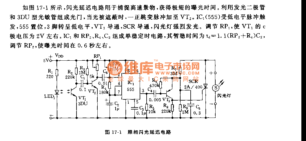
As shown in figure 17-1, the camera flash delay circuit is designed to capture high-speed scenes, allowing for very short exposure times. The light gate consists of a luminous diode and a 3DU type photosensitive tube. When the light...
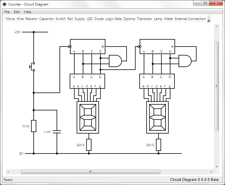
This is Circuit Diagram 0.1 Alpha Software, available for free download and open source. The Circuit Diagram 0.1 Alpha Software is designed as an intuitive platform for creating and editing electronic circuit schematics. It provides users with a variety of...