
TDA1562Q Audio Amplifier Circuit

The described electronic circuit operates primarily as a BTL (Bridge-Tied Load) amplifier, which is capable of delivering an output power of up to 18 W under normal conditions. The design incorporates a mechanism to elevate the internal supply voltage through the use of external electrolytic capacitors, enabling the amplifier to achieve a significant output power of 70 W when required. This feature is particularly advantageous for applications involving music signals, where dynamic range and transient response are critical.
The heatsink is a crucial component in this design, as it must effectively dissipate heat generated during operation, especially at higher power levels. The thermal management system should be capable of maintaining the device's case temperature below 120 °C to ensure reliable performance and prevent thermal shutdown. If the temperature exceeds this threshold, the amplifier automatically transitions from class-H operation to class-B operation, which reduces the output power to a safer level of 20 W. This automatic switching mechanism enhances the device's longevity and reliability by protecting it from overheating.
Furthermore, the amplifier is designed with a safeguard feature that mutes the output immediately if the supply voltage drops below a critical minimum level. This protection ensures that the amplifier does not produce unwanted noise or distortion during low-voltage conditions, thereby maintaining audio quality and preventing potential damage to connected speakers. Overall, the amplifier's design reflects a balance between performance, thermal management, and protection mechanisms, making it suitable for various audio applications.At low output power, up to 18 W, the device operates as a normal BTL amplifier. When a larger output voltage swing is required, the internal supply voltage is lifted by means of the external electrolytic capacitors. Due to this momentarily higher supply voltage the obtainable output power is 70 W. The heatsink should be designed for use with music signals. If the case temperature exceeds 120 °C, the device will switch back from class-H to class-B operation. The high power supply voltage is then disabled and the output power is limited to 20 W. When the supply voltage drops below the minimum operating level, the amplifier will be muted immediately.
🔗 External reference
Related Circuits
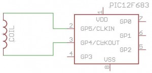
How to build your own RFID system using a microcontroller. This schematic is very simple. Building a Radio Frequency Identification (RFID) system using a microcontroller involves several key components and a straightforward schematic design. The essential elements of an RFID...
A 20-band equalizer for a 900-watt MOSFET power amplifier. The output level would decrease by the amount of resistors, so for two equal resistors, it should be amplified by a gain of 3. The first schematic is a simple...
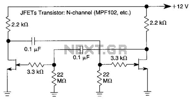
The use of JFETs allows for high resistance and long time constants in this very low frequency multivibrator. The values indicated are for operation at 0.15 Hz. In the context of electronic circuit design, a multivibrator is a circuit that...
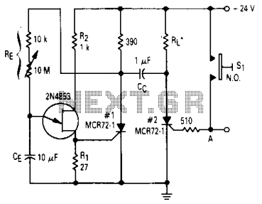
After one cycle of operation, SCR1 will be activated, resulting in a low voltage being applied to the UJT emitter circuit, which interrupts the tuning function. When pushbutton SI is pressed, or a positive pulse is applied at point...
The microphone preamplifier circuit design presented in this schematic utilizes the SSM2015 component manufactured by Precision Monolithics Inc. (PMI). This component provides high amplification with low noise characteristics (1.3nV/f). The design is configured to handle differential input signals and...
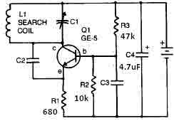
This metal detector circuit requires a power supply of 9 volts (DC) or a 9-volt battery. The circuit includes a variable capacitor C1 valued at 365 pF, a 100 pF silver mica capacitor C2, a 0.05 µF disc capacitor...