
Third harmonic excitation device automatic circuit a thyristor

The circuit design encompasses a harmonic generator that operates through dedicated stator windings, specifically tailored for third harmonic voltage generation. This configuration utilizes thyristor rectification to manage the output voltage effectively. The system is engineered to adapt to varying load conditions through automatic excitation control, which optimizes performance and stability.
The interaction between the generator load and the power factor is critical. When the generator experiences increased load, the power factor tends to diminish, leading to an elevation in the third harmonic output voltage. This response is vital for maintaining the operational integrity of the generator under varying electrical demands. Conversely, a reduction in load prompts an increase in the power factor, resulting in a proportional decrease in the third harmonic voltage. This dynamic adjustment ensures that the generator operates efficiently across a range of conditions.
In scenarios where a short circuit occurs on the grid, the output voltage from the third harmonic winding can experience a significant surge. This phenomenon triggers the force field generator, which serves as a protective and corrective mechanism, safeguarding the overall system from potential damage due to excessive voltage levels.
The schematic representation in Figure 7-43 provides a visual layout of the harmonic excitation winding, illustrating the interconnections and components involved in the system. This figure is essential for understanding the circuit's operational principles and for troubleshooting any issues that may arise during its operation. Overall, the design emphasizes reliability and adaptability in managing harmonic voltages within electrical systems. Attached to a separate harmonic generator stator windings, leads to the third harmonic voltage thyristor rectifier supply made after the motor field. Since the output voltage v aries with the winding harmonics generator load changes, and therefore with automatic adjustment of excitation. When the generator load and increase power factor decreases, the third harmonic winding output voltage corresponding increase; when the generator load decreases and the power factor increases, the third harmonic winding voltage correspondingly reduced.
When the grid a short circuit, the third harmonic winding output voltage is greatly increased, the implementation of the force field generator. Circuit shown in Figure 7-43. Figure, sQ harmonic excitation winding.
Related Circuits
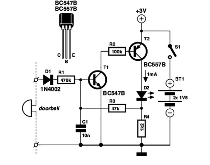
If you are expecting an important visitor but need to step out for a moment, an electronic doorbell memory can be useful to check who rang the bell. An electronic doorbell memory system is designed to capture and store the...
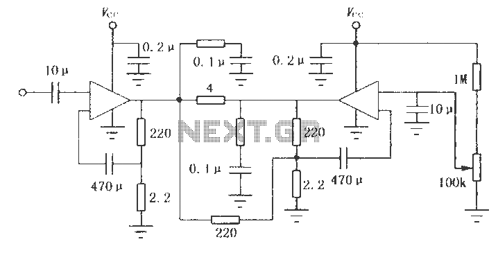
The LM2002 / 2002A is an audio power amplifier integrated circuit. The LM2002A features high voltage protection, with a maximum instantaneous power supply voltage of up to 40V, and comes in a 5-pin single in-line plastic package. This integrated...

The schematic below illustrates four methods of controlling a relay with a digital logic signal. Figure A can be used in most cases where the relay coil requires 100 mA or less and the input current is 2 milliamps...
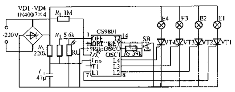
The ASIC is a flashing light string controller featuring four outputs. It includes a single key cycle control with six different lighting effects, and it allows for the selection of either 16 or 8 patterns. The circuit incorporates a...
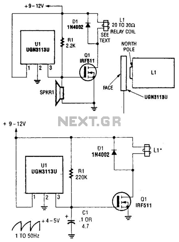
Although not intended for this application, a Hall-effect switch can be utilized as the foundation for an unconventional oscillator. The oscillator can be reconfigured, as illustrated in Fig. B, to enable the circuit's oscillating frequency to be regulated through...
The circuit comprises a 3-stage resistor-capacitor coupled amplifier. When ring button S2 is pressed, the amplifier circuit formed around transistors T1 and T2 gets converted into an asymmetrical astable multivibrator generating ring signals. These ring signals are amplified by...