
Positive And Negative Voltage Switching Supply

The LT1172 is a versatile integrated circuit designed to provide both positive and negative output voltages from a single 5-V input source. Operating as a step-up (boost) converter, it utilizes an inductor to increase voltage levels efficiently. The configuration of the LT1172 allows for the generation of a negative output voltage through the implementation of a charge pump circuit.
In this setup, the inductor plays a critical role in energy storage and voltage conversion. During the switching cycle, when the internal power switch of the LT1172 is closed, current flows through the inductor, causing it to store energy. The diode D2, which is oriented to allow current flow in one direction, becomes forward-biased during this phase. As a result, the inductor charges the capacitor C2, which acts as a reservoir for the stored energy.
Once the power switch opens, the energy stored in the inductor is released. The sudden change in current causes the voltage across the inductor to reverse. Consequently, the positive terminal of capacitor C2 is pulled to ground, allowing the stored energy to discharge into capacitor C4. This discharging process generates the negative voltage output required for various applications.
The design of the LT1172 ensures that both the positive and negative outputs are stable and can handle varying load conditions. The use of external components such as inductors, capacitors, and diodes must be carefully selected to optimize the performance of the circuit, taking into account factors such as ripple voltage, load current, and efficiency. Overall, the LT1172 provides a compact and efficient solution for dual voltage generation in electronic applications. An LT1172 generates positive and negative voltages from a 5-V input. The LT1172 is configure d as a step-up converter. To generate the negative output, a charge pump is used. C2 is charged by the inductor when D2 is forward-biased and discharges into C4 when LT1172"s power switch pulls the positive side of C2 to ground.
Related Circuits
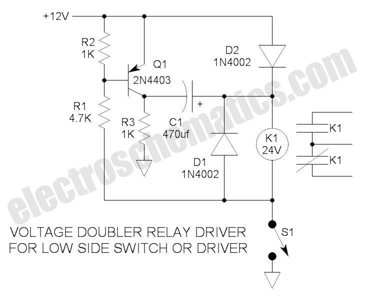
These novel relay driver circuits have the capability to activate a relay with a coil voltage rating that is double the supply voltage (Vcc). Once the relay is activated, the armature is maintained using Vcc, resulting in a significant...
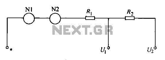
A voltmeter operates through a measuring mechanism in a specified circuit, utilizing a moving coil in series with additional resistance. The fixed coil is denoted as N1, while the moving coil is designated as N2. The additional resistances are...
These power supply circuits generate 500 volts, but they can be modified to supply several hundred to nearly 1000 volts by changing the zener diodes. These circuits produce high voltages and can cause dangerous shocks. Caution is advised; these...
Four simple 12V power supply circuits are designed to provide output voltages close to 12V. The first power supply circuit utilizes a BD139 transistor, a zener diode, and several passive components. Each schematic is straightforward to assemble and will...
Sometimes amateurs like to home-brew their power supplies instead of purchasing one off the shelf at any of the major ham radio retail dealers. The advantage to rolling your own power supply is that it teaches us how they...
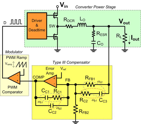
Before designing with one of today's powerful buck regulator ICs, it is essential to have a thorough understanding of voltage mode control and compensation. Voltage mode control is a widely used method in switching power supplies, particularly in buck converters....