
Simple Safety Circuit Circuit

The two-hand safety control switch is designed to enhance safety in applications where the operation of machinery or equipment could pose a risk to the operator. By requiring both pushbutton switches to be activated simultaneously, the system ensures that the operator maintains a safe distance from the moving parts or hazardous areas.
In this configuration, each pushbutton switch is connected in series, meaning that the circuit is only completed when both switches are pressed. The switches are typically momentary contact types, which means they return to their default position when released. This design prevents accidental activation of the relay and ensures that the machinery remains in a safe state when the operator's hands are not in the correct position.
The relay, which is energized when both switches are pressed, can control larger loads or more complex machinery, acting as an interface between the low-power control circuit and the high-power operational circuit. It is essential to select a relay that is rated for the load it will control, ensuring reliability and safety in operation.
In addition, it is advisable to implement additional safety measures such as emergency stop buttons and visual indicators to further enhance the safety of the system. Proper labeling and training for operators are also critical to ensure that the two-hand control mechanism is used correctly, thereby minimizing the risk of accidents. The simple two-hand safety-control switch shown here is little more than two pushbutton switches connected in series; both must be depressed in order to energize the relay.
Related Circuits
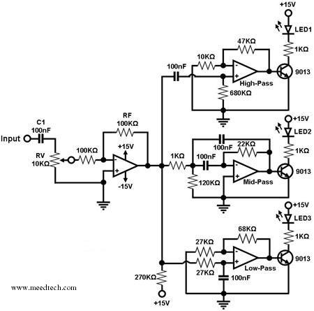
A simple circuit for converting an audio signal (such as one that comes from the output terminals of a CD player). The circuit basically consists of a buffer/amplifier stage and three filter circuits: a high-pass filter, a mid-pass filter,...
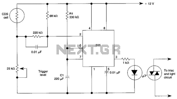
This circuit can control the on/off cycle of a light using a CDS photocell and turn it off after a preset period. The light can only be activated when the CDS cell is in darkness, and it remains on...
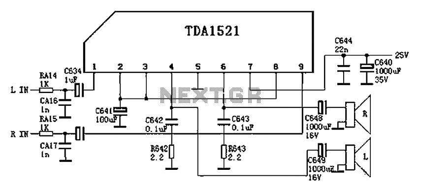
Color is often used in audio circuits like the TDA1521, which is derived from the Changhong C2191 model featuring an OTL two-channel connection. The pin functions and reference voltages for the TDA1521 are as follows: Pin 1: 11V -...
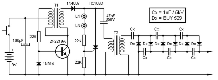
This high voltage source consists of an inverter built around a transistor that generates pulses of 150V. These pulses are supplied to an inverter made of a thyristor and a capacitor, which is connected in series with transformer T2....
This circuit consists of two main components: a battery charger that provides a fixed output voltage of 5V DC, and a regulated power supply that allows for an adjustable output voltage ranging from 2 to 9 volts. The circuit design...
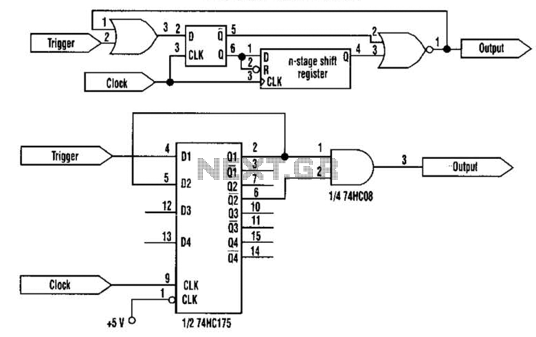
This approach utilizes a Hip-Hop, a shift register, and two gates (A). Before the one-shot pulse, the output of the NOR gate is 0. Consequently, the data input of the D-type flip-flop is equivalent to the trigger. When a...