
One of debug circuitry DC motor armature resistance in series starting

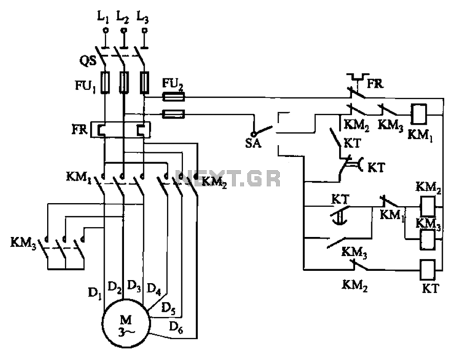
The circuit design illustrated in Figure 3-190 is a robust solution for controlling the operation of a motor through an armature circuit. The configuration of two startup resistors, Ri and Rz, serves to limit the inrush current during the initial startup phase, which is critical for protecting the motor and associated components from damage due to excessive current draw. The relays KTi and KTz play a pivotal role in the automatic disconnection of these resistors, ensuring that the motor transitions smoothly to full operational voltage after the startup phase.
The integration of over-current protection (KIl) and weakening protection (KI2) enhances the reliability of the system by providing safeguards against conditions that could lead to motor failure. The intermediate relays KA and KA are essential for monitoring under-voltage conditions, which can prevent potential damage caused by insufficient voltage levels during operation.
The functionality of the main switch SA is crucial in this circuit. By shifting the switch from the 0 position to the 1 position, the operator initiates the startup sequence. The timing of the relays is carefully calibrated to ensure that the resistors are shorted at the correct intervals, allowing the motor to reach its full operational capacity without undue stress. The option to adjust the master switch SA to positions 2 or 3 provides flexibility in controlling the motor's speed and torque by varying the resistance in the armature circuit, thereby allowing for tailored performance based on specific operational requirements.
Overall, this circuit design exemplifies a well-thought-out approach to motor control, incorporating essential protective measures and providing adjustable operational parameters to meet diverse application needs. Circuit shown in Figure 3-190. The line in the armature circuit in series two startup resistor Ri, Rz, through the main switch SA to achieve start, stop and speed control. Duri ng startup time by two relays KTi, KTz automatically cut two segments startup resistor. With over-current protection circuit (KIl) and weakening protection (KI2). Intermediate relay KA, KA for the under voltage relay. At startup, the SA from 0 position hit the 1 position, the startup resistor Ri, Rz have access armature circuit via a delay after paragraph (determined by KTi) short of Ri, and then after a delay ( KT2 decision) by the short and the Rz, electric full voltage running into the motive, the end of the boot process. If desired deceleration can be master switch SA is set to 2 or 3 position, the motor armature in series level or resistance levels run under.
Related Circuits
Electronics tutorial about DC motors, electrical motors, and stepper motors used as actuators, including PWM and transistor H-bridge motor control. DC motors, electrical motors, and stepper motors are integral components in various applications, functioning as actuators to convert electrical energy...
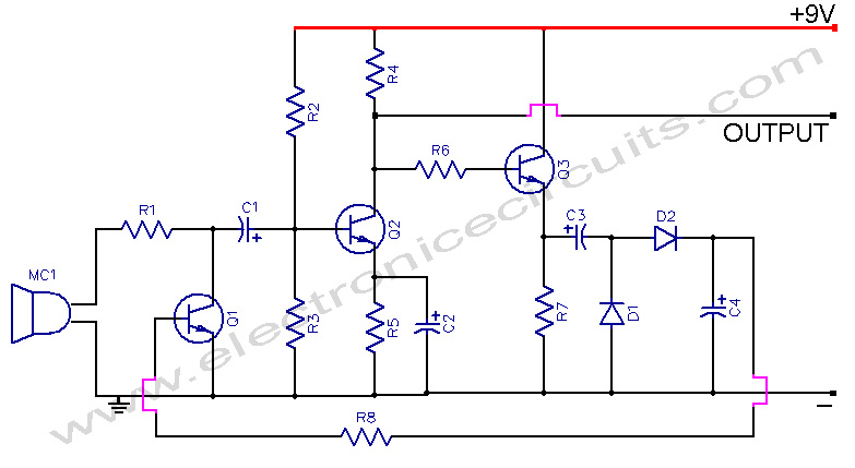
This microphone preamplifier incorporates automatic gain control, which keeps the output level fairly constant over a wide range of input. The microphone preamplifier is designed to enhance the audio signal from a microphone while maintaining a consistent output level. The...
The circuit depicted in Figure 3-98 demonstrates how motor starting and low-speed operation are managed using switch SA. By adjusting the time relay KT, the motor's operation can transition from low speed to high-speed operation within a specified time...
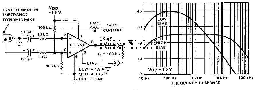
A microphone preamplifier utilizing a CMOS operational amplifier powered by its own battery is compact enough to fit within a small microphone casing. The amplifier functions with a 1.5V battery and exhibits low supply currents. This preamplifier operates at...
The soft start circuit refers to a power circuit where the output voltage gradually increases to a specified value, thereby protecting the load circuit from unwanted voltage surges. It can output a voltage of 24V and a current of...
The circuit is illustrated in Figures 16-95 to 16-97. The electrode automatic adjuster demonstrates enhanced performance, featuring a high-accuracy, well-linear current output type bridge. Additionally, it incorporates a differential arc current negative feedback circuit (advanced) that allows for preemptive...