
Using reactors buck breeze block circuit

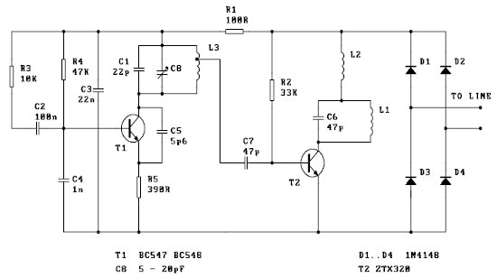
The circuit consists of a loop reactor governor, which is a critical component in controlling the performance of electrical systems. The series reactor is employed to limit the current and improve the stability of the system by providing a controlled inductance. The use of a TV choke indicates that the reactor is designed to handle high-frequency signals, making it suitable for applications that require noise suppression and signal integrity.
The physical construction details specify that the reactor is built with a strength wire, which contributes to its durability and effectiveness. The dimensions of the wire, with a length of 40-50mm and a diameter of 6mm, are chosen to optimize the inductance while minimizing resistance. The specified number of turns, between 200 and 300, is critical for achieving the desired inductive properties, and the insulation is essential to prevent short circuits and ensure safe operation.
In practical applications, this loop reactor governor circuit can be utilized in various electronic systems, including power supplies and motor drives, where precise control of current and voltage is necessary. Proper implementation of this circuit can lead to enhanced performance, reduced electromagnetic interference, and improved overall efficiency of the electrical system. The careful selection of components and construction techniques ensures reliability and longevity in operation. Circuit shown in Figure 3-2. That is in the original loop reactor governor again a series reactor. Reactor available TV choke on, can also be made: with such. About 3mm high st rength wire, a length of 40-50mm M6mm bolt turns around 200-300, and deal with good insulation.
Related Circuits
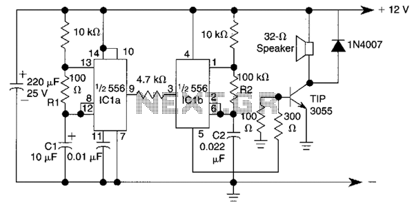
This circuit utilizes a 556 timer IC to initially generate a low-frequency square wave, which is then modulated to produce two alternating tones of approximately 400 Hz and 500 Hz. The circuit is designed to create a warble alarm...
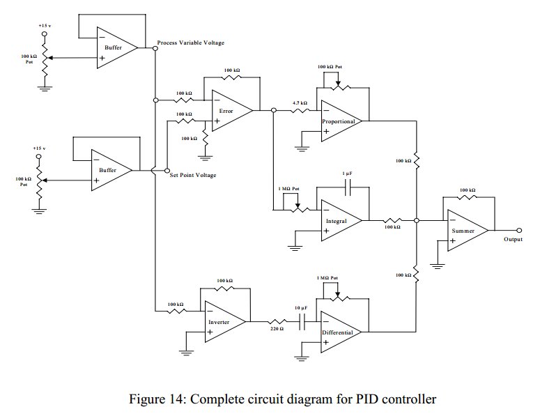
Convert a feedforward operational amplifier PID loop to C code. Assistance is needed for this conversion, as the process is unfamiliar. Input values can be obtained through an ADC, such as voltage or current, but coding a feedforward PID...
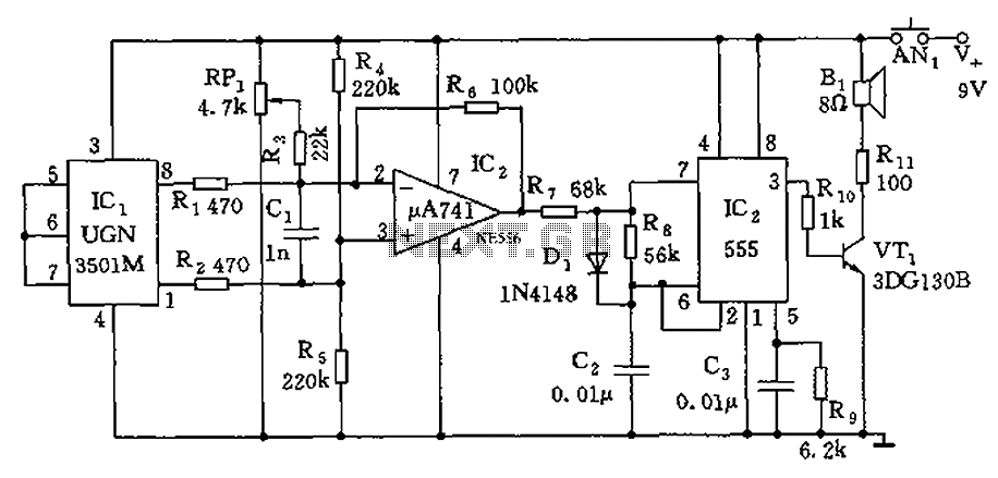
The circuit consists of a 555 timer and associated components designed for voltage-to-frequency conversion. It is utilized for determining the orientation of Earth's magnetic field using a Hall-effect sensor, specifically the UGN-3501M. This sensor incorporates a Hall element and...
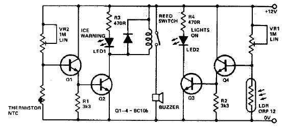
This electronic project circuit diagram for an ice warning and lights reminder system alerts drivers when their vehicle lights should be activated and warns them if the outside temperature approaches zero degrees Celsius. The system employs an LED indicator...
This is a basic telephone broadcaster or transmitter designed for eavesdropping on telephone conversations. The circuit can also function as a wireless telephone amplifier. A key feature of this phone transmitter is that it derives its power directly from...
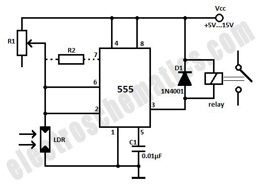
This light-activated relay circuit utilizes the 555 timer integrated circuit (IC) and a light-dependent resistor (LDR) to create a light-sensitive relay suitable for applications such as intruder alarm systems or automatic lamp control at sunset and sunrise. The potentiometer...