
Spy Phone Bug Transmitter Circuit

This telephone broadcasting circuit employs a simple yet effective design to enable eavesdropping on conversations. The automatic switching mechanism integrates various components, ensuring low power consumption while maintaining functionality. The use of a voltage divider formed by resistors R1 and VR1 is critical for controlling the operational state of the transistors. The zener diode plays a pivotal role in regulating the switching voltage, allowing for precise control over the circuit's activation and deactivation based on the telephone line's voltage.
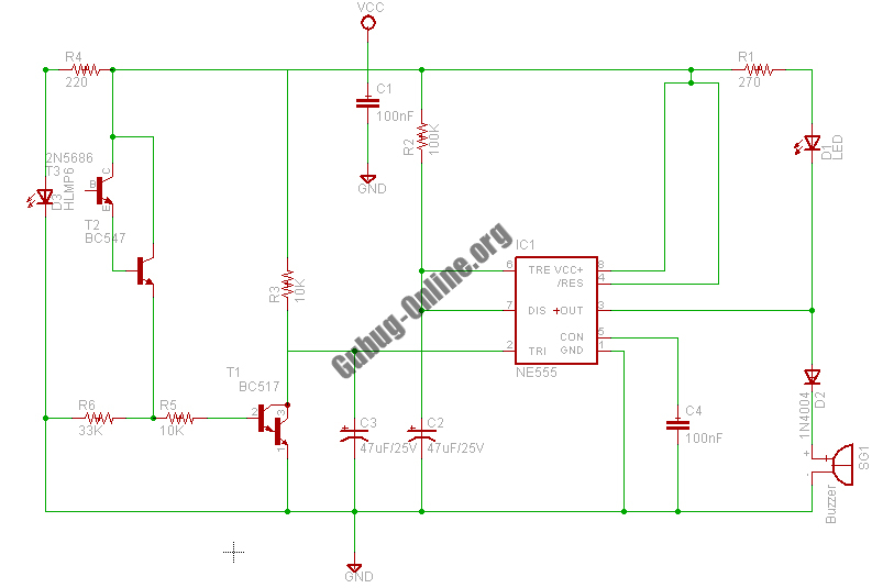
In the FM transmitter section, the common-emitter configuration of transistor T3 allows for efficient modulation of the RF signal, which is essential for transmitting audio signals over a distance. The inclusion of coil L1 aids in establishing the oscillation frequency, further enhancing the circuit's performance. The circuit's compact design enables it to be discreetly integrated into existing telephone infrastructure, making it a practical solution for wireless amplification and monitoring of telephone conversations. The overall design emphasizes efficiency, low power usage, and ease of installation, making it suitable for various applications in telecommunications and audio transmission.A very simple telephone broadcaster or transmitter which can be used to eavesdrop on a telephone conversation. The circuit can also be used as a wireless telephone amplifier. One important feature of this phone transmitter is that the circuit derives its power directly from the active telephone lines, and thus avoids use of any external ba
ttery or other power supplies. This not only saves a lot of space but also money. It consumes very low current from telephone lines without disturbing its performance. The phone bug transmitter is very tiny and can be built using a single -IC type veroboard that can be easily fitted inside a telephone connectin box of 3. 75cm x 5cm. Automatic switching section comprises resistors R1 to R3, preset VR1, transistor T1 and T2, zener D2 and diode D1.
Resistor R1, along with preset VR1, works as a voltage divider. When voltage across the telephone lines is 48V DC, the voltage available at wiper of preset VR1 ranges from 0 to 32V (adjustable). The switching voltage of the circuit depends on zener breakdown voltage and switching voltage of the transistor T1.
Thus, if we adjust preset VR1 to get over 24. 7 volts, it will cause the zener to breakdown and transistor T1 to conduc. As a result collector of transistor T1 will get pulled towards negative supply, to cut off transistor T2. At this stage, if you lift the handset of the telephone, the line voltage drops to about 11V and transistor T1 is cut off.
As a result, T2 gets forward biased through R2 to provide a DC path for T3 used in the following FM transmitter section. The low-power FM transmitter section comprises oscillator transistor T3, coil L1 and a few other components.
T3 works as a common-emitter RF oscillator, with T2 serving as an electronic on/off switch. The audio signal available across the telephone lines automatically modulates oscillator frequency via T2 along with its biasing R3. The modulated RF signal is fed to the antenna. The telephne conversation can be heard on an FM receiver remotely when it is tuned to the transmitter frequency.
🔗 External reference
Related Circuits

Each J202 JFET stage provides up to 180 degrees of phase shift controlled by a 1 megohm potentiometer. The potentiometer allows for complete control of the groups. JFETs are ideal for the designated circuit because they do not load...

The schematic for this tutorial is illustrated below and includes all necessary components for the tutorial to function. The PIC programming circuitry is not included, as it is assumed that the PIC is either programmed externally or that the...

Originally, the tank cost around Php 400 but was later sold for approximately a hundred pesos less. Recognizing a great deal, the decision was made to purchase the toy. Opening the toy proved to be somewhat challenging. The track...
This design circuit project involves a clear glass sensor circuit intended for experimental or hobbyist applications. The concept is straightforward and relies on a homemade sensor unit that includes one high-efficiency ultra-bright red LED (D1) and a standard phototransistor. The...
The circuit operates as an astable multivibrator, generating a square wave signal at a specific frequency. When powered, the circuit will function continuously. The astable multivibrator circuit is a type of oscillator that produces a continuous square wave output without...
The DW L11 capacitor steps down voltage into the Jenru half crossing according to Yin electrical specifications. After receiving power at the bin CI SH output terminal, it regulates the voltage to liVI/r j, ensuring a right cut in...