
It can send a signal to start forward rotation start circuit

The circuit operates by integrating an audio output component, such as a piezo buzzer or speaker, which generates a distinct startup sound when the motor is activated. This auditory signal serves as an alert to operators that the motor is in the process of starting. Concurrently, a visual indicator, typically an LED, emits a light signal that remains illuminated until the motor has successfully reached its operational state. Once the motor is fully operational, the circuit is designed to deactivate both the sound and light signals, providing clear feedback to the user that the startup sequence has been completed.
To enhance safety, the circuit may include additional features such as overload protection, which prevents the motor from starting under excessive load conditions. This can be achieved through the use of current sensors that monitor the motor's input current. If an overload is detected, the circuit can be designed to interrupt the power supply to the motor, thereby preventing potential damage and ensuring safe operation.
Moreover, the circuit can be configured with a delay timer to allow for a gradual increase in motor speed, further minimizing mechanical stress and enhancing the longevity of the equipment. This functionality can be implemented using a microcontroller or a simple RC timing circuit, depending on the complexity required.
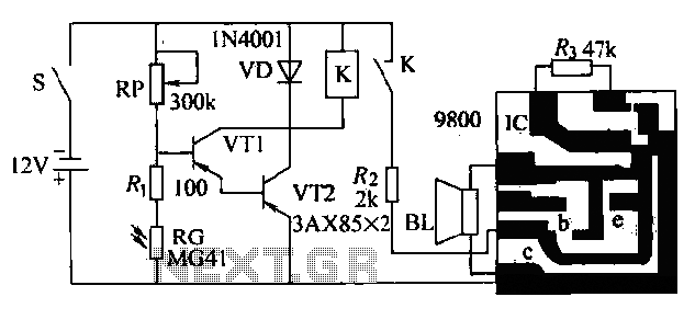
In summary, the circuit not only provides auditory and visual feedback during the motor startup process but also incorporates safety measures to protect the machinery and ensure reliable operation across a diverse range of applications. Circuit shown in Figure 3-21. It issued motor startup sound, light signal to start the process is completed, the signal stops. This circuit is adapted to drive the motor by mea ns of a large range of movement of machinery and equipment, to ensure safety.
Related Circuits

The circuit provides an 8-ohm output for connecting communication receivers and low-impedance speakers or headphones, featuring harmful interference suppression for continuous random voice transmission. The passband ranges from 55 to 2530 Hz with a 3 dB bandwidth. Inductors L1...

The infrared transmitter circuit, as depicted in Figure 18-la, utilizes transistors VT1 and VT2 along with RC components to create an astable multivibrator. The circuit operates with VT1 and VT2 receiving base bias from resistors, and closing switch SA...
The circuit presented is a second-generation flame alarm for natural gas stoves. After the gas stove is ignited and normal combustion occurs, the power switch S is closed. The photoresistor RG, influenced by the light from the flame, has...

It is a wireless doorbell with a cost of about $10.00. This product encourages a shift in approach to building projects, utilizing such items to learn about their functions and modify them to meet specific needs. The doorbell incorporates...

A phase control circuit can be utilized to regulate the power supplied to an AC load. This circuit modulates the AC waveform by cutting portions of the cycle. A phase control circuit is an essential component in various applications where...

The automatic emergency light circuit has the following features: 1. When the mains supply (230V AC) is available, it charges a 12V battery up to 13.5V, after which the battery is disconnected from the charging section. 2. When the...