
Phase Control Circuit

A phase control circuit is an essential component in various applications where the modulation of AC power is required. The primary function of this circuit is to adjust the phase angle of the AC waveform, effectively controlling the amount of power delivered to the load. This is achieved by using semiconductor devices such as thyristors or triacs, which can turn on and off at specific points during each AC cycle.
In a typical phase control circuit, the control mechanism begins with the detection of the zero-crossing point of the AC waveform. Once the zero-crossing is detected, the circuit introduces a delay before allowing the AC voltage to pass through to the load. This delay is referred to as the phase delay, and it determines how much of the waveform is cut off. By varying this delay, the average power delivered to the load can be finely adjusted.
The circuit may include additional components such as a microcontroller or an opto-isolator for enhanced control and safety. The microcontroller can be programmed to adjust the phase delay based on various input parameters, such as temperature or load conditions, thus providing a dynamic response to changing operational requirements.
The output of the phase control circuit can be connected to resistive loads, inductive loads, or even capacitive loads, depending on the specific application. However, care must be taken to ensure that the circuit can handle the switching transients and potential noise generated during operation, which may require the inclusion of snubber circuits or filters.
Overall, the design and implementation of a phase control circuit are critical for applications such as light dimmers, motor speed controllers, and heating elements, where precise control over AC power is necessary.A phase control circuit can be used to control the power delivered to an AC load. The phase control circuit control the AC waveform, cutting the cycle to give. 🔗 External reference
Related Circuits

This 555 timer circuit is a remote control jammer device that is useful for blocking the use of remote controls, particularly when children frequently change channels or settings. The 555 timer is a versatile integrated circuit that can be configured...
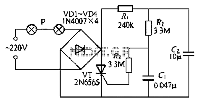
A simple and easy-to-implement one-way flashing lights string controller is designed for small shop or home decoration. This device utilizes a thyristor-based dimmer circuit, which operates effectively by managing large capacitance. The circuit includes a ten-microfarad capacitor connected to...
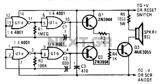
An external horn-type speaker is optimal for this circuit. However, such devices demand significant power, so this sounder should only be employed in alarm circuits utilizing at least a 6-A SCR as the sounder driver. The circuit incorporates a...
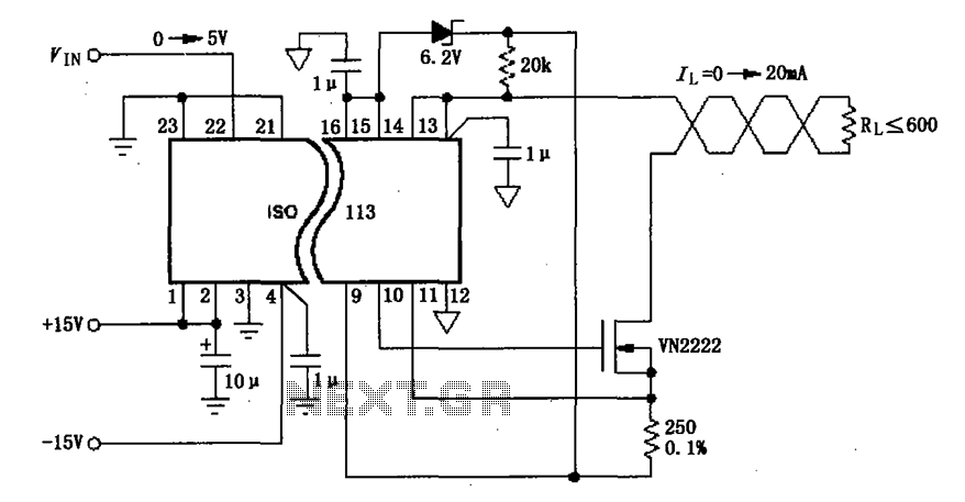
The circuit depicted in the figure consists of an ISO113 current loop isolation drive circuit that operates with an input signal (VIN) to provide an isolated amplified output of 0 to 20 mA. This current is transmitted to the...
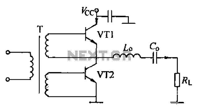
A complementary voltage switching Class D amplifier circuit is presented. Transistors VT1 and VT2 are 3DA12 types, while another transistor, VT3, is of the 3DK41C type. The collector is connected to a constant DC voltage of 12V. The input...
The circuit is based on a single operational amplifier integrated circuit designed to produce a modular preamplifier that operates in Class A configuration. The modular preamplifier circuit utilizes a single operational amplifier (op-amp) integrated circuit, which serves as the primary...