
Start reversing contactor interlock control circuit

The circuit in question is likely part of a motor control system, specifically designed for controlling the direction of a motor's rotation. The forward contacts (KMi) and forward buttons (SBi) allow the operator to initiate forward motion, while the reverse contacts (KMz) and reverse buttons (SB2) enable reverse motion. The stop button (SB3) is a critical safety feature that allows the operator to halt the motor's operation quickly.
In this setup, pressing the forward button (SBi) energizes the forward contactor (KMi), closing its contacts and allowing current to flow to the motor in the forward direction. Conversely, when the reverse button (SB2) is pressed, the reverse contactor (KMz) is energized, redirecting the current to the motor in the opposite direction. It is essential to ensure that both forward and reverse buttons cannot be activated simultaneously to prevent short circuits or damage to the motor.
The stop button (SB3) is typically wired in a way that interrupts power to both contactors when pressed, ensuring the motor is immediately de-energized. This arrangement may include additional safety mechanisms, such as overload protection or emergency stop features, to enhance operational safety.
In designing this circuit, it is crucial to consider the ratings of the contactors and buttons to handle the motor's current and voltage requirements. Additionally, proper wiring practices should be followed, including the use of fuses or circuit breakers to protect against overloads. The layout of the circuit should minimize the risk of electrical noise and interference, which can affect the operation of the control buttons and contactors.
Overall, this circuit represents a straightforward yet effective means of controlling motor direction and operation, with safety and reliability as primary design considerations. Circuit shown in Figure 3-22. Figure, KMi and SBi are forward contacts and forward buttons, KMz and SB2 are reverse contactors and reverse button, SB3 for the stop button.
Related Circuits
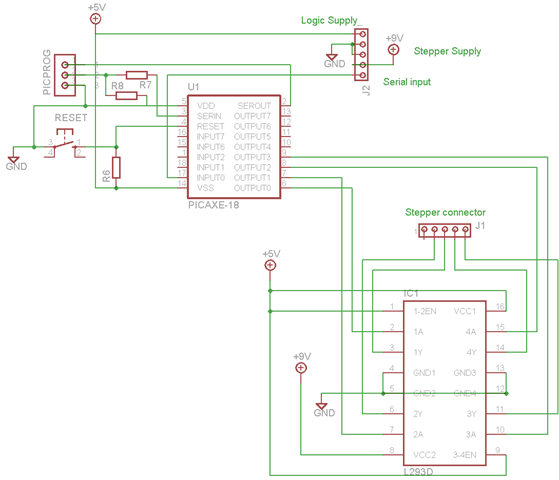
A schematic and program have been developed for operating a bipolar stepper motor through a serial interface, similar to the unipolar configuration. This is significant for the robot arm project, as two of the three stepper motors will be...
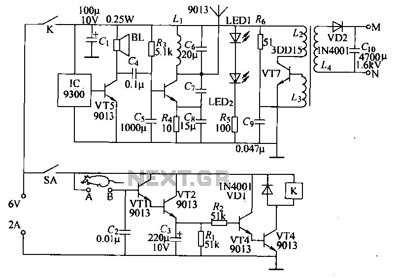
Power-saving electronic mousetrap. This example describes the minimal power consumption, which only occurs when a mouse enters the control zone during foraging activities. After a 30-second delay, the system enters a wait state, making it suitable for outdoor use....
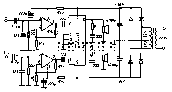
The first power amplifier circuit illustrated in Figure 5-88 utilizes the NE5532 operational amplifier, configured as a line amplifier, and features the TDA1521 power amplifier. This circuit operates with a dual power supply and eliminates the need for coupling...
This circuit features a microphone and preamplifier that take precedence over any other audio signal, functioning similarly to a one-way intercom. When the push-to-talk switch is activated, the main amplifier switches from music playback to the voice signal. Essentially,...
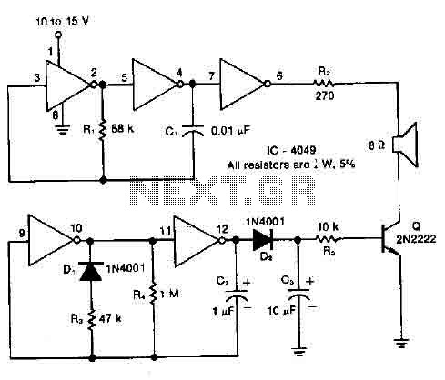
A resistor R1, capacitor C1, and two converters create a square wave generator that produces a fundamental tone. This generator is followed by an inverter that functions as both a buffer and a driver for the system. Resistor R2,...
The receiver provides two TV signals, one for the living room and another for the bedroom, along with a satellite receiver. Watching television in the bedroom is convenient in Taiwan; however, when watching television in the living room, it...