
Bipolar stepper motor control with Picaxe and L293D

The schematic for the bipolar stepper motor control includes a microcontroller that communicates via a serial interface, allowing for precise control over the motor's operation. The bipolar stepper motor is characterized by its two coils, which must be energized in a specific sequence to achieve rotation. The microcontroller sends commands to a motor driver circuit, which handles the directional control and current flow to the coils.
In this configuration, the driver circuit typically employs H-bridge topology, enabling the reversal of current through the coils. This is essential for the bipolar motor operation, as it requires alternating current direction to step through its phases. The program running on the microcontroller includes algorithms for step control, allowing the motor to achieve desired speeds and positions based on input commands.
To ensure reliable operation, the schematic should incorporate necessary components such as current limiting resistors, flyback diodes for back EMF protection, and decoupling capacitors to stabilize the power supply. The choice of microcontroller and driver IC should be compatible with the required voltage and current specifications of the bipolar stepper motors.
Additionally, it is vital to consider the power supply requirements, as bipolar stepper motors typically require higher current ratings compared to unipolar motors. Proper heat dissipation measures should also be integrated into the design to prevent overheating of the driver circuit during prolonged operation.
In summary, the developed schematic and program provide a comprehensive solution for controlling bipolar stepper motors in robotic applications, enabling precise movement and positioning essential for the functionality of the robot arm.I`ve now got a schematic and program for running a bipolar stepper motor via a serial interface (just as for the unipolar case). This is important for the robot arm cause because two of the three steppers will be of the bipolar kind.
Where driving the unipolar stepper required only current `pushing` (ie all in. 🔗 External reference
Related Circuits
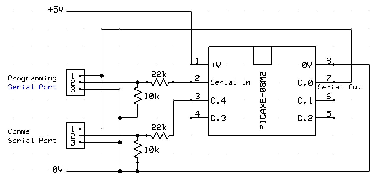
A tutorial on setting up RS232 communication with PICAXE, including a circuit diagram, serial cable configuration, PC communication program setup and configuration, along with sample code for PICAXE. The RS232 communication setup for PICAXE microcontrollers is essential for enabling serial...
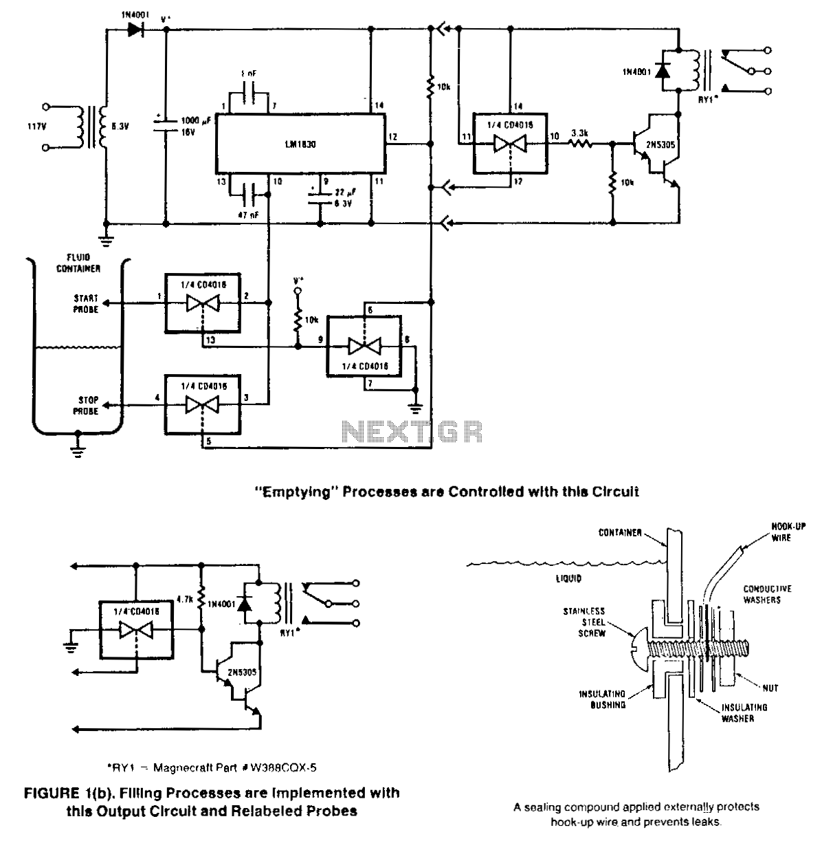
This circuit is designed to detect the presence or absence of aqueous fluids. An AC signal generated on-chip is passed through two probes within the fluid. A detector determines the presence of the fluid by using the probes in...
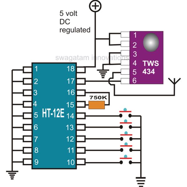
This document explains two RF 433kHz remote control chips specifically designed for remote control applications. The IC TWS-434, along with its encoder chip HT-12E from Holtek, forms a high-quality transmitter circuit, while the chip RWS-434, paired with the decoder...
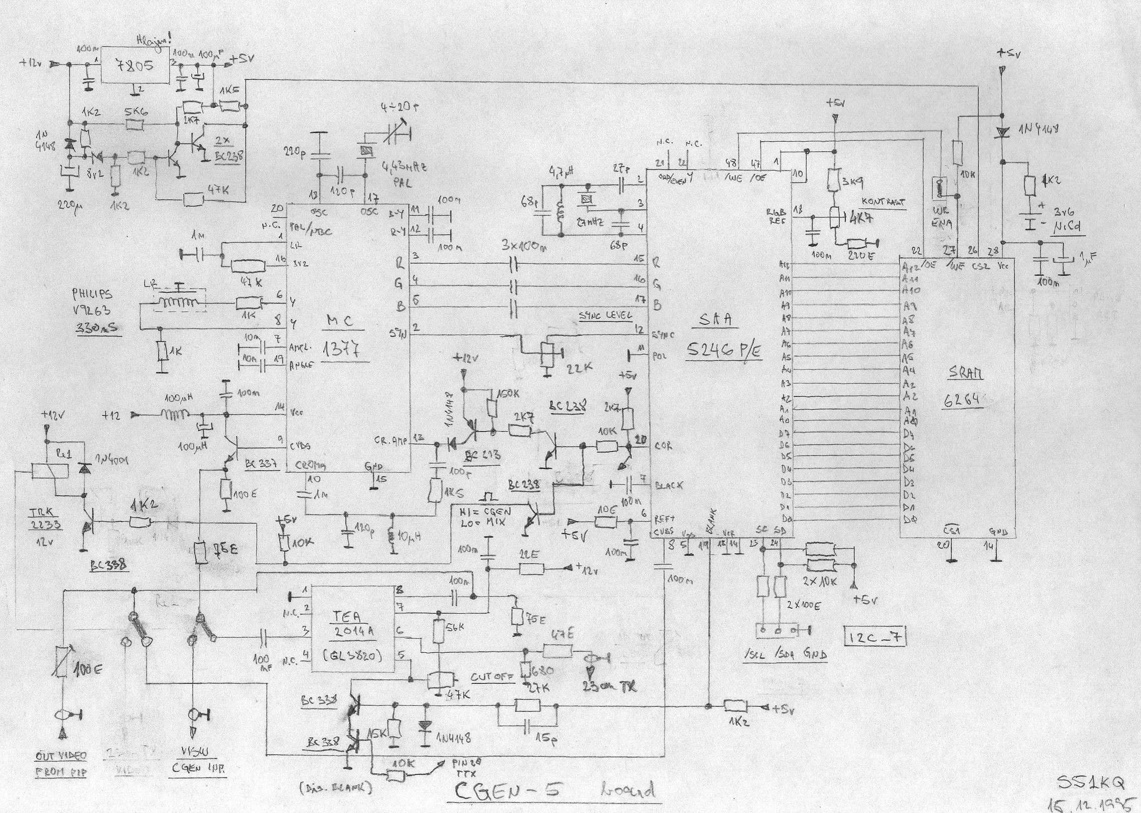
This is an image Schematic. No Description available. The provided input indicates that there is an image schematic without any accompanying description. In scenarios where a schematic is presented, it typically contains graphical representations of electronic components and their...
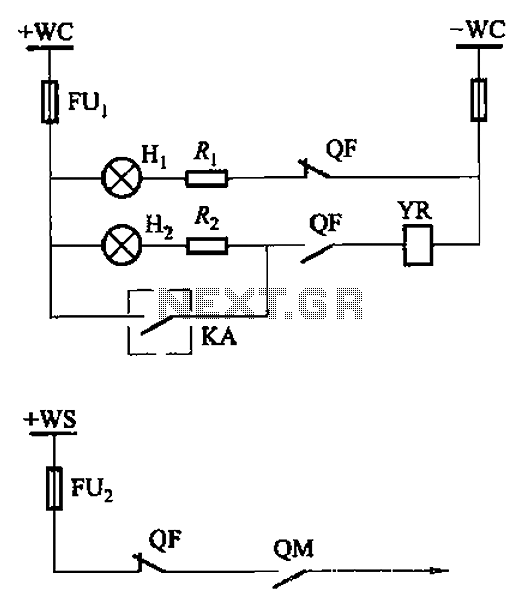
The CS2 type is a manually operated breaker mechanism commonly utilized for AC power operation and manual control signal circuits, as depicted in Figure 6-68. The circuit includes various components: wc for small signal bus control, QF for auxiliary...
120V galvanic acupuncture salmon RI. The system features a wind-down rectification and a limit irrigation mechanism to achieve an amplitude of 24V. It includes isolation diodes and a steady stream over the circuit. The design ensures that a voltage...