
Amplifier circuits

The described circuit utilizes a complementary push-pull configuration, which is commonly employed in audio amplifier designs to enhance efficiency and reduce distortion. In this setup, Q3 (NPN) and Q4 (PNP) transistors work together to amplify the audio signal. The complementary nature of these transistors allows for both halves of the audio waveform to be amplified, which is critical for maintaining signal integrity and achieving high fidelity in audio applications.
The circuit typically includes biasing resistors that ensure the transistors operate in their active regions, minimizing crossover distortion that can occur when transitioning between the two transistors. Additionally, feedback mechanisms may be implemented to stabilize the gain and improve linearity across a range of frequencies.
Power supply considerations are also crucial; the circuit must be designed to handle the required voltage and current levels for moderate power output, ensuring that the transistors remain within their safe operating areas. Heat dissipation must be managed effectively, often through the use of heat sinks, to prevent thermal runaway and ensure reliable long-term operation.
Overall, this complementary push-pull amplifier configuration is a robust solution for moderate power audio amplification, providing a good balance between performance, efficiency, and thermal management.Note, Q3 and Q4 in Figure below are complementary, NPN and PNP respectively. This circuit works well for moderate power audio amplifiers. For an explanation of this circuit see Direct coupled complementary-pair, Ch 4. 🔗 External reference
Related Circuits
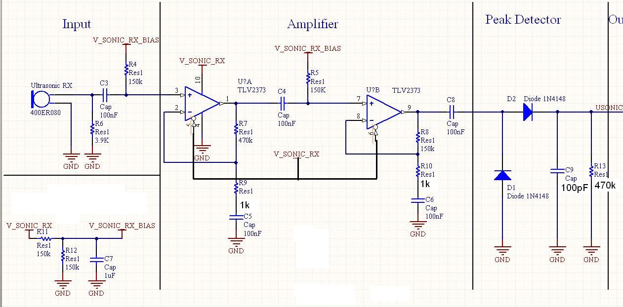
It has been mentioned that the operational amplifier (op amp) in the second stage may be damaged. Confirmation is requested by testing the op amp in a buffer configuration or any simple configuration. This test is necessary to ascertain...
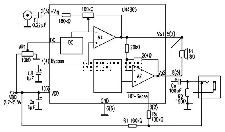
A 750mW bridge-tied load audio amplifier circuit utilizing the LM4065 amplifier is presented below. The LM4865 is available in an 8-pin SO package and an 8-pin mini SMD package. The power supply voltage (VDD) ranges from 2.7V to 5.5V,...
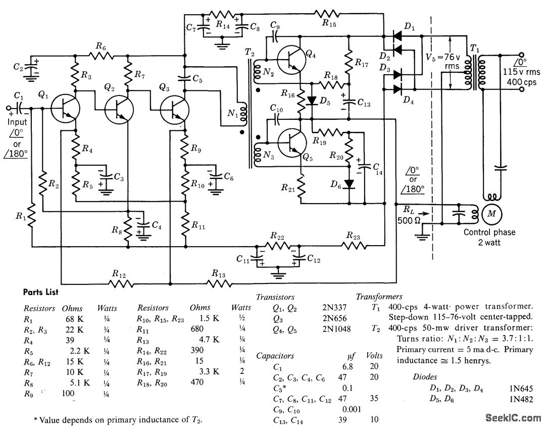
The circuit comprises a direct-coupled preamplifier and driver stages, featuring significant direct current (d-c) feedback to stabilize bias conditions. The voltage gain of the amplifier, when the feedback loop is closed, is 10,000. The overall efficiency of the circuit...
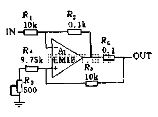
In a servo system, the current drive connection is frequently utilized. The output current (IOUT) is proportional to the input channel number (y). Using the current drive mode can mitigate issues caused by the motor's large inductance, which induces...
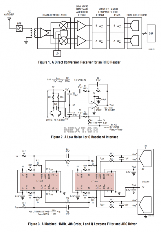
Figure 1 shows the block diagram of a direct conversion RF receiver—the receiver demodulates an RF carrier directly into a baseband signal without an intermediate frequency down-conversion (a zero IF receiver). The antenna, shared by both the transmitter and...
A simple yet effective amplifier unit characterized by low distortion. A similar modification was employed in the HAFLER preamplifier. The quality of the reproduced sound in all symmetrical amplifiers remains consistent, regardless of the cost of materials, including transistors,...