
BLY94 50W RF Amplifier Circuit

The FM RF power amplifier circuit utilizing the BLY94 transistor is designed for efficient signal amplification in the FM broadcasting range of 88-108 MHz. The BLY94 is a high-frequency transistor known for its ability to handle significant power levels, making it suitable for applications in FM transmitters.
In this configuration, the circuit achieves a power gain of 8dB, which indicates a substantial increase in output power relative to the input. The design emphasizes the importance of using quality components, particularly trimmers and coils, which are critical for tuning and stability. These components help to optimize the circuit's performance by minimizing losses and ensuring that the amplifier operates within its intended frequency range.
The input stage of the amplifier is designed to accept an RF power level of 7W, which is sufficient to drive the BLY94 into its optimal operating region. The output stage, capable of delivering up to 50W, is ideal for broadcasting applications, where high power is required to ensure a strong signal over a wide area.
Careful attention should be paid to the layout of the circuit to reduce parasitic capacitance and inductance, which can affect performance at high frequencies. Additionally, proper heat dissipation mechanisms must be implemented to prevent thermal damage to the transistor during prolonged operation.
Overall, this FM RF power amplifier circuit represents a robust solution for FM transmission needs, combining high power output with efficient gain characteristics, suitable for a variety of broadcasting applications.This fm rf power amplifier circuit is built with BLY94 transistor which delivers up to 50W at 175MHz and has a power gain of 7dB, arround 5x power amplification. But in this schematic bly94 is working in 3 meter band, FM 88-108 MHz, so it has a higher power gain, 8dB 6x.
So if we use a good quality trimmers and coils with 7W input rf power BLY 94 will deliver up to 50W rf power. 🔗 External reference
Related Circuits
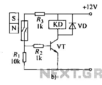
The automatic weapon features a magnetic switch circuit that is simple, reliable, has a low failure rate, and offers good versatility. It can be used to output performance or convert mechanical displacement. The circuit diagram utilizes a Hall switch...
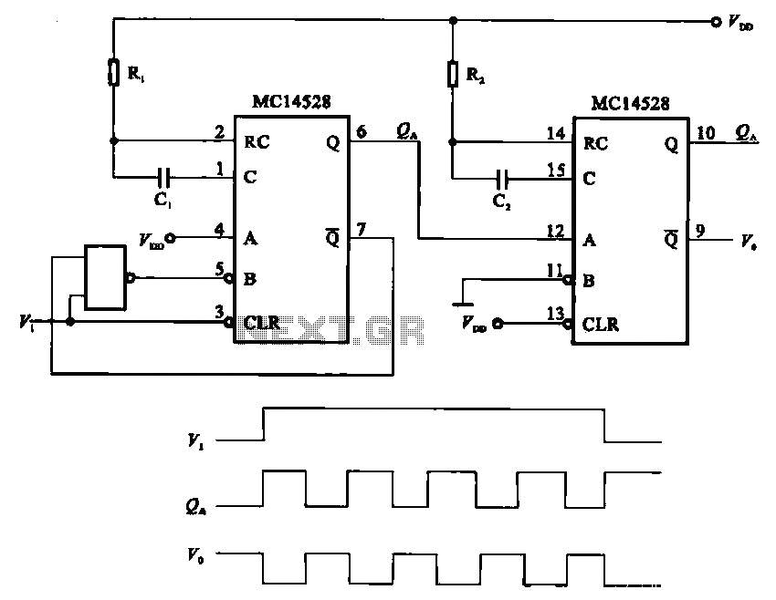
The pulse generating circuit monitors signals using monostable flip-flops. It generates a single-shot output signal based on the input pulse signal. A key signal from the monostable flip-flops is represented in a formula, with the input (V1) and output...

XTAL1 drives amplifier Q3/Q4, which is tuned to 2.25 MHz. The detected signal is fed to audio amplifier IC1. A 9-V supply is used. The circuit operates at 2.25 MHz and is designed to be used with an ultrasonic...

The Wien-Bridge oscillator meets specific requirements due to the presence of a low-pass filter, a high-pass filter, and a 180-degree phase shift from the feedback networks connecting the input to the output. This configuration results in a total phase...

This is a high-fidelity, high-quality audio amplifier circuit diagram. A pre-amplifier is not required. Component list: R1, R4 = 47K 1/4W resistors; R2 = 4.7K 1/4W resistor; R3 = 1.5K 1/4W resistor; R5 = 390Ω 1/4W resistor; R6 =...

The IR2156 provides a cost-effective solution for fluorescent electronic ballasts. It integrates features such as lighting tube error protection and a programmable working frequency, which includes warm-up, lighting, and continuous operation of the ballast. The IR2156 is a highly integrated...