
Slave Flash Trigger

In electronic circuit design for camera systems, the integration of supplementary lighting is crucial for improving visibility in low-light conditions. A common solution involves the use of LED (Light Emitting Diode) arrays, which provide efficient illumination while consuming minimal power. The circuit typically includes a power supply unit, a control circuit, and the LED array.
The power supply unit must be designed to convert the available voltage to the required level for the LEDs, taking into account the forward voltage and current specifications for the chosen LED components. A DC-DC converter can be employed for this purpose, ensuring that the LEDs receive a stable voltage and current, thus prolonging their lifespan and maintaining consistent brightness.
The control circuit can be implemented using a microcontroller or a simple transistor-based switch. If using a microcontroller, it can be programmed to adjust the brightness of the LEDs based on ambient light conditions, using a light-dependent resistor (LDR) as a sensor. The LDR detects the level of surrounding light and sends this information to the microcontroller, which then modulates the LED brightness accordingly. This allows for optimal illumination without excessive power consumption.
In summary, the design of a supplementary lighting circuit for cameras in low-light environments involves careful consideration of power management, control mechanisms, and component selection to ensure effective performance and energy efficiency.Using any camera in a dull or dark environment generally requires the use of supplementary light. This is a standard technique, and even where adequate na.. 🔗 External reference
Related Circuits
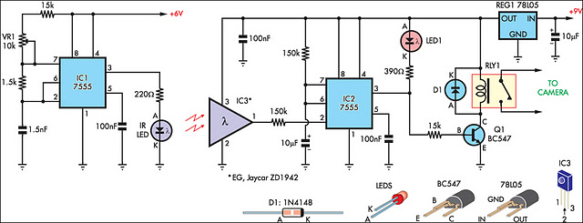
This circuit serves as an alternative to the infrared (IR) beam break detector featured in the June 2009 issue of Silicon Chip. To enhance its insensitivity to ambient light, it employs a standard IR receiver integrated circuit (IC), such...

The circuit's input operational amplifier triggers the timer, setting its flip-flop and cutting off its discharge transistor so that capacitor C can charge. When the capacitor voltage reaches the timer's control voltage (0.3Vcc), the flip-flop resets, and the transistor...

A 100W resistance-triggered motor control circuit designed for arc welding machines. It features an adjustment potentiometer (Rr) that can modify the DC motor excitation current. Additionally, a regulator (RP) is included to adjust the DC motor armature voltage, enabling...
It allows car headlights to flash on and off simultaneously or alternately. Components: 555 IC, transistor, resistor, relay, polarized capacitor. The circuit utilizes a 555 integrated circuit (IC) in a monostable or astable configuration to control the flashing of car...
All components have been placed on the PCB, but there is uncertainty regarding the connection of the power and load in relation to the relays. The integration of relays into a printed circuit board (PCB) design requires a clear understanding...

5 WAY AC FLASHER. These types of circuits are commonly used in various ceremonies such as the Wesak festival, Christmas, and weddings. This 5 WAY AC FLASHER circuit. The 5 Way AC Flasher circuit is designed to produce a sequential...