
0-60sec start-stop timer with 555

The described timer circuit utilizes the NE555 timer IC, which is a versatile and widely used component in various timing applications. The circuit is designed to generate adjustable time intervals ranging from a few seconds up to approximately 60 minutes, making it suitable for a wide range of applications.
The component values specified in the circuit are as follows:
- R1 (1KΩ), R2 (10KΩ), R3 (4.7KΩ), R4 (1KΩ), R5 (10KΩ), R6 (4.7KΩ), R7 (1KΩ) are resistors that help set the timing intervals.
- RV (2.2MΩ) is a variable resistor that allows for fine-tuning of the timing duration.
- D1 (1N914) is a diode used for protection against reverse polarity and to control the discharge path of the timing capacitor.
- C1 (100nF) is a timing capacitor that, in conjunction with the resistors, determines the charge and discharge time, thereby controlling the duration of the timer.
- C2 (100µF/16V) serves as a filter capacitor to stabilize the power supply for the circuit.
- IC1 is the NE555 timer IC itself, configured in either astable or monostable mode depending on the desired operation.
- T1 (BC547) is a transistor used to amplify the output signal from the NE555 timer to drive the relay.
- RY is a 12V relay that acts as the output switch, allowing the circuit to control larger loads with the timer's output.
This circuit can be easily modified by changing the resistor and capacitor values to adjust the timing range and scale according to specific requirements. The relay output enables the timer to control various devices, making it a flexible solution for applications requiring timed operations.This timer is ideal for small aplications. Due to its simple structure, its usage and nevertheless its universal character, this mini timer is usable in the most current applications needing time intervals, from some seconds through approximately 60 minutes. By simple modifications it is possible to adjust the maximum time and the timing scale, as necessary.
A strong output, made by a relay, permits to adapt, on the input and the output, whatever apparatus.
The circuit is constructed around the classical timer NE555. Parts: R1=1K R2=10K R3=4K7 R4=1K R5=10K R6=4K7 R7=1K RV=2M2 D1=1N914 C1=100nF C2=100uF/16V IC1=NE555 T1=BC547 RY=12V RELAY
Related Circuits
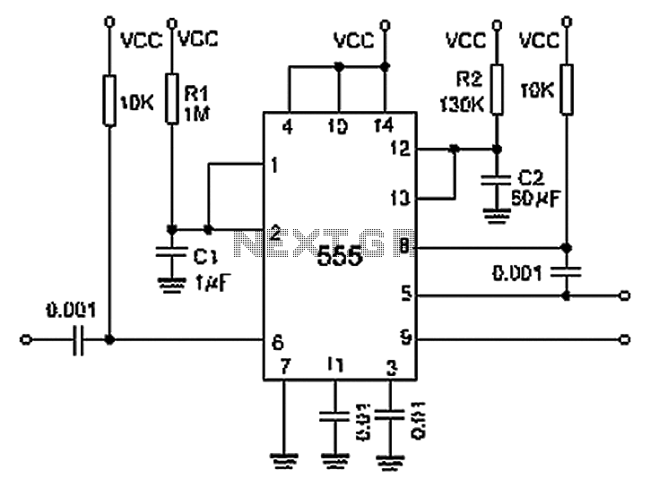
A 0.001 F coupling capacitor connects the output of the first half of a 556 timer to the input of the second half, providing an individual delay that equals the total delay. The 6-foot ground can immediately activate the...
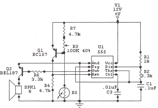
The IC 555 Light Alarm (Sun Up Alarm) is a circuit designed to emit a loud alarm at dawn, particularly beneficial for individuals who struggle to wake up even with a traditional alarm clock. The circuit can be modified. The...
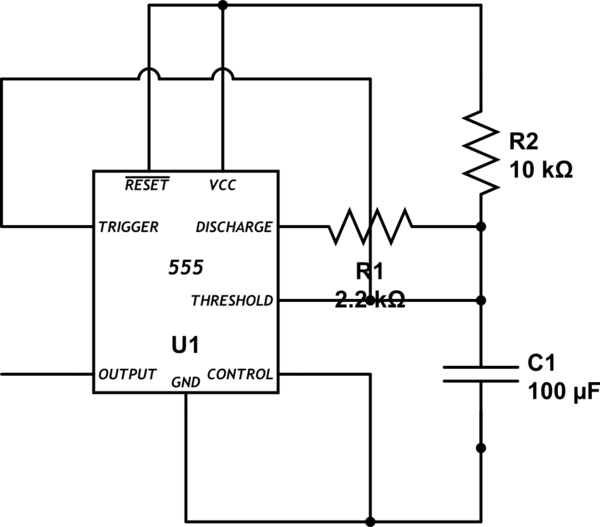
Bold lines indicate soldered connections, while arrows represent wire-based connections. Red indicates V_cc, black represents ground, blue signifies intermediate connections, and gold denotes the primary output. Pins 1 and 5 are connected to ground. It is noted that pin...
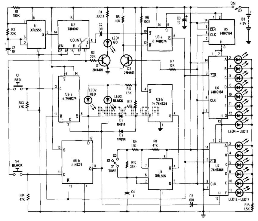
This circuit utilizes a timer to produce pulses at a 5-ms clock rate. The pulses are sequentially shifted into a shift register, illuminating an LED. An auxiliary timer generates one pulse per second to activate the "go" LED and...
AT89S52 for Bell Timer Circuit Diagram. Features: 7-segment display is replaced with LCD display. DS1307, uses AT89S52 microcontroller and I2C. The circuit utilizes the AT89S52 microcontroller, which is an 8-bit microcontroller from the Atmel 8051 family. This microcontroller is programmed...
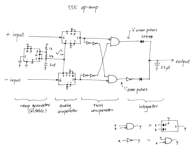
Is it feasible to create an operational amplifier using only 555 timer chips and passive components? While this may not be a practical inquiry, given the availability of low-cost and efficient op-amps, it does have some aesthetic interest. In...