
AT89S52 For Bell Timer

The circuit utilizes the AT89S52 microcontroller, which is an 8-bit microcontroller from the Atmel 8051 family. This microcontroller is programmed to manage the timing functions of the bell timer, providing precise control over timing intervals. The integration of the DS1307 real-time clock (RTC) allows for accurate timekeeping, enabling the circuit to activate the bell at specified times.
The circuit design incorporates an LCD display in place of a traditional 7-segment display, enhancing readability and allowing for more information to be displayed simultaneously. The LCD is connected to the AT89S52 via the I2C (Inter-Integrated Circuit) protocol, which simplifies the wiring and communication between the microcontroller and the display.
In terms of functionality, the bell timer circuit can be programmed to set specific times for the bell to ring, making it suitable for applications such as alarms, reminders, or notifications in various environments. The user can interact with the system through input buttons connected to the microcontroller, allowing for easy adjustments to the timer settings.
Overall, this circuit design combines the capabilities of the AT89S52 microcontroller with the precision of the DS1307 RTC and the user-friendly interface of an LCD display, resulting in an efficient and effective bell timer solution.Description: AT89S52 For Bell Timer Circuit Diagram. Features: 7segment display is replaced with LCD display. DS1307, uses AT89S52 microcontroller and I2C .. 🔗 External reference
Related Circuits
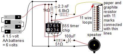
A simple music instrument/keyboard is created using a 555 timer chip circuit, a piece of paper, and a pencil. The project includes a more advanced automatic music player that utilizes a playing head and a long sheet of paper...
The most challenging aspect of this circuit was determining its title. It can be easy to overlook the sound of a doorbell while watching television; this circuit addresses that issue by providing a visual indication, such as a lamp....
This 555 timer circuit activates a relay upon pressing a button. The threshold and trigger inputs, pins 2 and 6, are maintained at half the supply voltage by two 10K resistors. When the output is high, a capacitor charges...
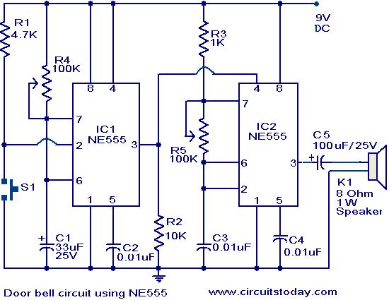
The primary components of this doorbell circuit are two NE555 timer integrated circuits (ICs). When switch S1 is pressed momentarily, the loudspeaker emits a bell tone for the duration determined by the monostable multivibrator configuration around IC1. Pressing switch...
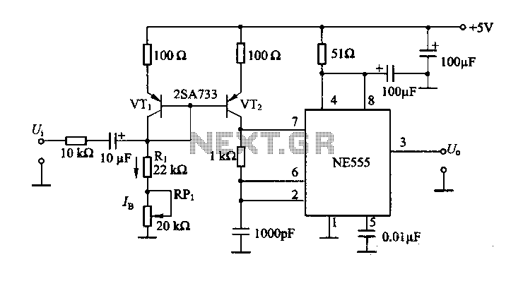
The circuit consists of a NE555 timer and a frequency modulation circuit that modifies the self-excited multivibrator NE555 by adjusting the charging current for frequency modulation. The components VT1 and VT2 form a current mirror circuit, which generates a...
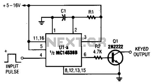
With switch SI in the off position, battery voltage is applied across timing capacitor CI, which remains charged while the rest of the circuitry is powered off. Transistor Q1, and consequently transistors Q2 through Q4, remain in an off...