
0 to 9 asynchronous decade counter 7490 display

The circuit utilizes the 7490 asynchronous decade counter, which is capable of counting from 0 to 9 in binary-coded decimal (BCD) format. The output pins of IC2 correspond to the BCD representation of the decimal digits. This output is fed into the 7446 decoder/driver (IC1), which translates the BCD signals into the appropriate signals required to illuminate the segments of the seven-segment display (D1).
The seven-segment display consists of seven individual LEDs, each labeled from 'a' to 'g', which represent the segments that can be illuminated to form the digits 0 through 9. In this particular configuration, a common anode type display is employed, meaning that all the anodes of the LEDs are connected together to a positive voltage supply, while the individual cathodes are connected to the output pins of the decoder. This configuration requires that the outputs of the 7446 be driven low to turn on the respective segments of the display.
To ensure proper operation and to prevent excessive current from flowing through the LEDs, current-limiting resistors (R1 to R7) are placed in series with each segment of the display. These resistors are calculated based on the supply voltage, the forward voltage drop of the LEDs, and the desired forward current to ensure longevity and reliability of the display.
The operation of the circuit is straightforward. Upon receiving a clock pulse, the 7490 counter increments its count, changing its BCD output. Each time this occurs, the 7446 decoder interprets the new BCD value and activates the corresponding segments of the display to show the appropriate digit. This allows for a visual representation of the count, making the circuit suitable for applications such as digital counters, timers, or frequency displays.The circuit is based on asynchronous decade counter 7490(IC2), a 7 segment display (D1), and a seven segment decoder/driver IC 7446 (IC1).The seven segment display consists of 7 LEDs labelled a through g. By forward biasing different LEDs, we can display the digits 0 through 9. Seven segment displays are of two types, common cathode and common anode. In common anode type anodes of all the seven LEDs are tied together, while in common cathode type all cathodes are tied together. The seven segment display used here is a common anode type .Resistor R1 to R7 are current limiting resistors.
IC 7446 is a decoder/driver IC used to drive the seven segment display. Working of this circuit is very simple. For every clock pulse the BCD output of the IC2 (7490) will advance by one bit. The IC1 (7446) will decode this BCD output to corresponding the seven segment form and will drive the display to indicate the corresponding digit. Email ThisBlogThis!Share to TwitterShare to FacebookShare to Google Buzz 🔗 External reference
Related Circuits
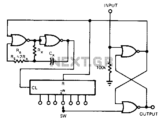
This CMOS circuit functions as a one-shot time delay switch and a general-purpose timer. It comprises a gated oscillator and a latch utilizing a CD4001 quad 2-input NOR gate, along with a CD4020 14-stage counter. The timing interval, TON,...
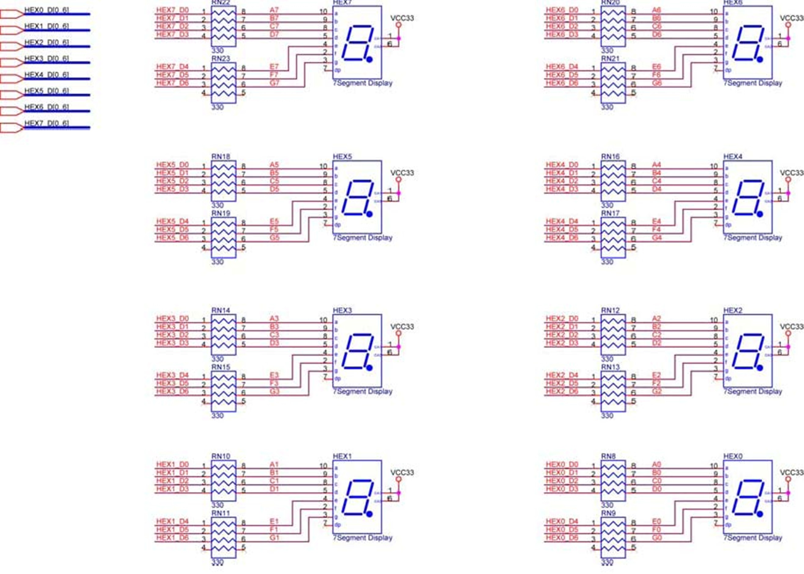
The DE2 Board features eight 7-segment displays arranged into two pairs and one group of four, designed for displaying numbers of varying sizes. According to the schematic in Figure 1, the seven segments are connected to pins on the...
This is an easy-to-build yet highly accurate digital voltmeter designed as a panel meter. It can be utilized in DC power supplies or any application requiring precise voltage readings. The circuit uses the CL7107 Analog to Digital Converter (ADC)...
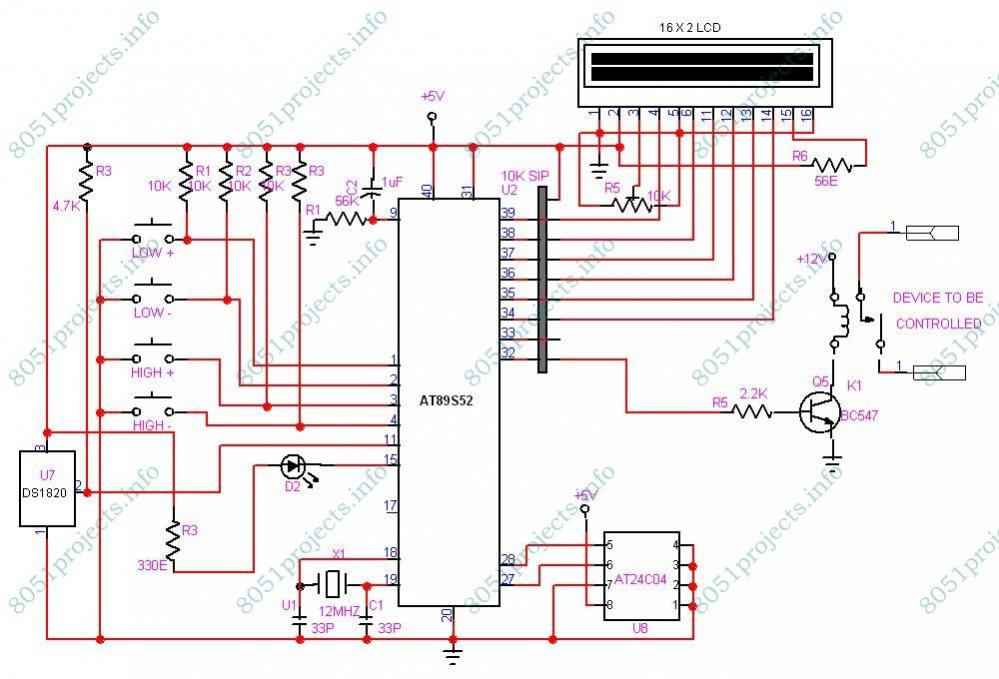
This project is designed to monitor and control temperature. The system utilizes the DS1820 temperature sensor to measure the temperature, which is then displayed on an LCD. It features two preset levels: a low preset and a high preset....
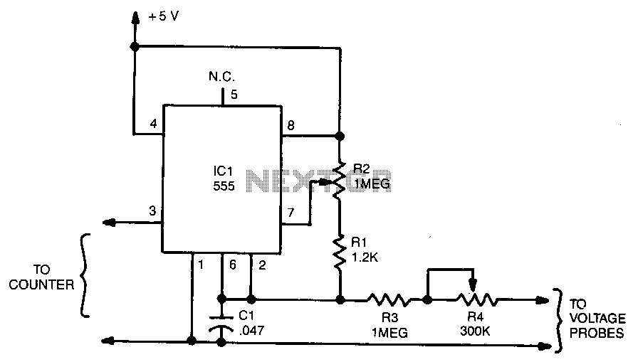
The output frequency from IC pin 3 is determined by the voltage input to pin 6. A standard frequency counter can be used to measure voltages directly over a limited range from 0 to 5 V. In this circuit,...
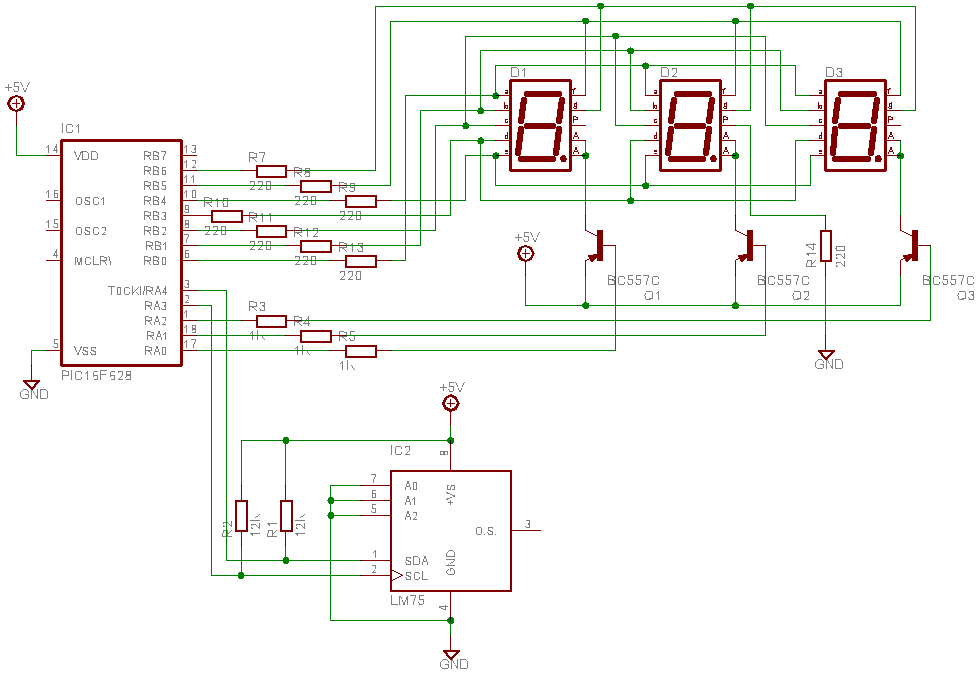
This is a test project assembled quickly on a solderless breadboard. It utilizes an LM75 temperature sensor to read the current temperature through the I2C communication protocol and displays the result. The project employs the LM75, a digital temperature sensor...