
1-2 MHz radio transmitter circuit diagram

The T1 low-impedance output transformer is designed to match the output of audio amplifiers to the impedance of loudspeakers, ensuring optimal power transfer and minimal signal loss. The transformer typically features primary and secondary windings that are configured to handle the specified impedance ratio of 5000 ohms on the primary side to 8 ohms on the secondary side.
In the schematic, the primary winding is connected to the amplifier output, while the secondary winding connects to the speaker load. The low-impedance design allows for efficient power delivery, making it suitable for various audio applications, including guitar amplifiers and hi-fi audio systems.
The circuit may also include additional components such as capacitors for filtering and protection, ensuring that high-frequency signals do not distort the audio output. Furthermore, the physical layout of the transformer should consider factors such as magnetic coupling and core material to optimize performance and minimize losses.
Overall, the T1 output transformer plays a critical role in audio signal integrity, providing a reliable interface between the amplifier and the speaker system while supporting the desired sound quality.A circuit diagram of the T1 is a low-impedance output transformer, it comes with 5000-8 ohm resistor.
Related Circuits
This sound-activated switch allows for control through sound, which can be beneficial not only in robotics but also in home automation applications. The sound-activated switch operates by detecting specific sound frequencies or patterns, typically using a microphone or a sound...
An electronic dice is a classic introductory project for individuals interested in electronics. It consists of a timer, counter, and several LEDs, forming a circuit that adds an engaging element to traditional board games. When the switch is activated,...
The circuit utilizes an integrated Hall effect sensor for an AC motor control system. It operates by detecting the presence of magnets or other magnetic objects near the Hall IC element of the induction motor. This configuration functions as...
The metal detector circuit includes a fixed frequency oscillator, mixer, detector, detection oscillator, and power amplifier circuit. The fixed frequency oscillator circuit is composed of a ceramic filter (ZC), transistor (V1), resistors (R1 to R4), capacitor (C2), and other...
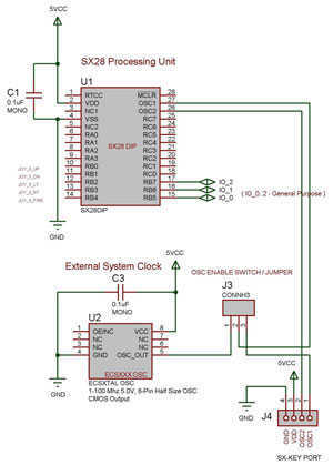
The SX 28 internal oscillator is not that fast, so an external oscillator can be hooked up to the processor as shown in the diagram to increase the operation cycles per second. The SX 28 microcontroller is designed with an...
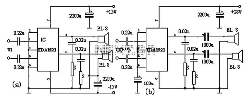
The TDA1521A amplifier circuit is designed for high-fidelity applications with minimal external components. It is suitable for powering Walkman devices or transforming low-powered computer speakers. The TDA1521A comes in a nine-pin single in-line plastic package and offers output power...