
electronic dice circuit

The electronic dice circuit utilizes a 555 timer in astable mode, which produces a continuous square wave output. This output serves as the clock signal for the BCD counter, typically a 74HC390 or similar IC, which counts from 0 to 9 in binary-coded decimal format. The counter is connected to a series of LEDs through a resistor network to limit the current and prevent damage to the LEDs. The arrangement of the LEDs simulates the faces of a die, with outputs corresponding to the values 1 through 6.
To ensure the output does not exceed the maximum value of 6, the two AND gates are strategically placed in the circuit. They monitor the BCD output, and when the count reaches seven, they send a reset signal to the BCD counter, forcing it back to one. This mechanism prevents the circuit from displaying an invalid die face.
The overall design can be enhanced by incorporating additional components, such as a debouncing circuit for the pushbutton switch, which would help to eliminate any unwanted multiple counts caused by mechanical bounce. Furthermore, a capacitor can be added to the 555 timer circuit to adjust the timing interval, allowing for customization of the dice rolling speed.
In summary, this electronic dice project combines fundamental electronic components, such as timers, counters, and logic gates, to create an engaging and interactive device that can enhance traditional gaming experiences. The design's simplicity and reliance on basic electronic principles make it an ideal project for beginners in the field of electronics.An electronic dice is a classic first project for those getting interested in electronics. A timer, counter and a few LEDs makes a circuit that can also add a new twist to some old boring board games. When the switch is pressed, a 555 timer in astable mode pulses a BCD counter which lights up a series of LEDs wired to mimic a dice.
Two AND gates a re used to reset the count back to one whenever the BCD output is seven. Thus, the circuit is not truly random but the natural bounce present in a pushbutton and the normal human ability to operate much slower then the oscillator make the output of the circuit seem random. 🔗 External reference
Related Circuits

HS101 and HS201 are small radio transceiver components operating at a frequency of 280 MHz, designed for digital signal transmission. They provide a control distance ranging from 30 to 100 meters. All components, including the antenna, are integrated into...
It's a very simple circuit, for the follow-up of baby. It can however be also used for other use, as intercom etc. In the place of M1 we can we use a simple electret mic capsule. The regulation of...

This document presents a circuit example for interfacing an RF module using the HT12E/D encoder-decoder pair. The attached circuit can be utilized for data transmission via the RF module, which is designed for single-channel operation, allowing only serial data...
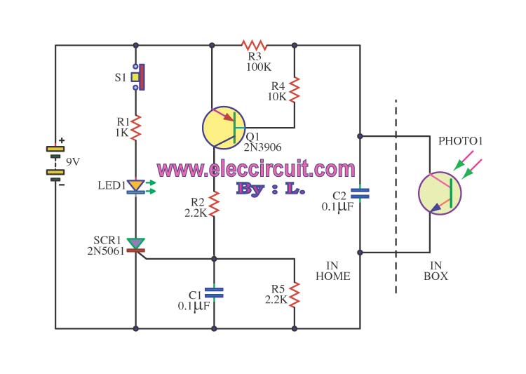
This is an integrated electronic mailbox circuit diagram designed for a front door. It activates when the door is opened. Additionally, when the cabinet photo detector is exposed to light, it will... The integrated electronic mailbox circuit is designed to...
Figure 7-2 illustrates the FSK (Frequency Shift Keying) signal demodulation circuit, which is built using a digital phase-locked loop. This circuit features two oscillators operating at distinct frequencies: crystal oscillator X with a frequency of 983.04 kHz and crystal...

A bipolar stepper motor drive circuit is presented, utilizing eight transistors to operate two phases. This bipolar drive circuit can accommodate both four-wire and six-wire stepper motors; however, it is primarily designed for four-wire bipolar configurations, which can significantly...