
1.5 Watt FM Transmitter
Components List:
- R1 = 10K
- C1 = 100uF/10V
- C2 = 10nF
- C3 = 4-40pF trimmer capacitor
- C4 = 4.7pF
- IC1 = LM3909
- Q1 = 2N3904 NPN transistor
- LED1 = Red LED or another color as desired.
The following diagram illustrates an FM transmitter circuit capable of 4W transmission. The voltage supply for this circuit ranges from 12V to 16V with a current consumption between 100mA and 400mA. This circuit operates within a frequency emission range of 88-108MHz. The components list includes:
- R1, R2 = 10K Ohm (1/4 W)
- R3 = 47 Ohm (1/4 W)
- C1, C2 = 1nF.
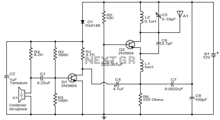
Additionally, a circuit diagram for a voice transmitter that utilizes an FM signal carrier to transmit voice signals to an FM receiver device is provided. The components list for this circuit includes:
- R1 = 4.7K
- R2 = 330 Ohm
- C1 = 0.001uF (1nF)
- C2 = 10-40pF
- C3 = 4.7pF
- Q1 = 2N3904
- L1 = as specified in the text
- Misc = Electret microphone.
This description encompasses the essential components and operational parameters of various FM transmitter circuits, highlighting their simplicity, cost-effectiveness, and suitability for educational purposes. The circuits are designed for efficient operation within specified voltage and current ranges, ensuring reliable performance in short-range transmission applications.P1 act as condenser microphone volume level. For FM, coil will be small. Use thin gauge enamel magnet wire. the diameter of coil will be a couple mm: use ink tube from pen to form, and try 8-12 turns. Small inductance coils make for much guess work. Tags: 1. 5 watt fm transmitter, circuit diagram fm transmitter, circuit diagram of fm transmitter, f m radio, fm transmitter, fm transmitter circuit, fm transmitter circuit diagram, radio circuit, radio transmitter, simple fm transmitter circuit, simple fm transmitter circuit diagram, transmitter circuit diagram, This is a low cost and easy build low powered FM transmitter. The range of the FM transmitter claimed about 300 feets when running at 9V supply. And the range claimed to be increased become about 400 feet when running it at 12V supply. Take a note that this transmitter should not be used as. This is probably the simplest radio transmitter that you will find anywhere. It has a total of five parts and can be constructed into a very small space. It is great for science fair projects or other science related projects where short range transmission is useful.
It runs on 1. 5 to 3 Volts, with small. Easy FM tracking transmitter project :). The circuit designed by Tony van Roon, and here the FM tracking transmitter diagram: Components List: R1 = 10K C1 = 100uF/10V C2 = 10nF C3 = 4-40pF trimmer capacitor C4 = 4. 7pF IC1 = LM3909 Q1 = 2N3904 NPN transistor LED1 = Red LED/or another color as you. The following diagram is the FM transmitter circuit with FM transmision up to 4W. Voltage supply for this circuit is 12-16V with current consumption of 100-400mA. This circuit works with frequency of emission range of 88-108MHz. Components List: R1, R2 = 10K Ohm (1/4 W) R3 = 47 Ohm (1/4 W) C1, C2 = 1nF. The following diagram is the circuit diagram of Voice Transmitter which use FM signal carrier to transmit the vioce signal to the FM receiver device.
Components List: R1 = 4. 7K R2 = 330 ohm C1 = 0. 001uF (1nF) C2 = 10-40pF C3 = 4. 7pF Q1 = 2N3904 L1 = see text Misc = Electret mike, . 🔗 External reference
Related Circuits
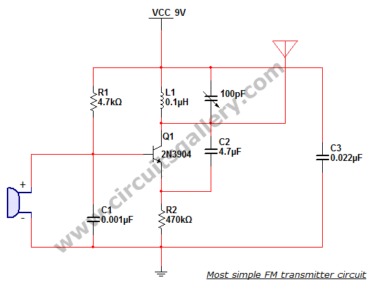
This is the simplest single transistor FM wireless transmitter circuit ever posted in CircuitsGallery. In the field of telecommunications, frequency modulation (FM) transmits information by altering the frequency of a carrier wave based on the message signal. FM utilizes...
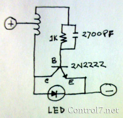
The LED is a fascinating component for amateur electronics hobbyists. The primary characteristic of an LED is that it requires a minimum of 3 volts to illuminate. Various circuits have been discovered to drive an LED using a single...
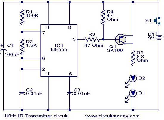
This circuit was designed in response to a request for a 1 kHz infrared (IR) transmitter circuit suitable for remote control applications. It is intended to serve as a low-power IR transmitter with an operating frequency of 1 kHz,...
This circuit features a very stable and simple FM transmitter design. This transmitter can achieve a range of approximately 200 meters when properly matched. The FM transmitter circuit typically consists of several key components: an oscillator, modulator, amplifier, and antenna....
Utilize this cell phone charger circuit along with a 1.5V battery when there is no main power available and charging your phone is necessary. This cell phone charger circuit is designed to provide a reliable charging solution using a 1.5V...
The amplifier of circuit uses negative current feedback. The load current depends mainly on the input signal and not so much on the impedance of the loudspeaker. The inductor current of the loudspeaker develops a voltage across R7. This...
Warning: include(partials/cookie-banner.php): Failed to open stream: Permission denied in /var/www/html/nextgr/view-circuit.php on line 713
Warning: include(): Failed opening 'partials/cookie-banner.php' for inclusion (include_path='.:/usr/share/php') in /var/www/html/nextgr/view-circuit.php on line 713