
Cell Phone Charger Using 1.5V Battery

This cell phone charger circuit is designed to provide a reliable charging solution using a 1.5V battery as the power source. The circuit typically consists of several key components, including a voltage regulator, a charging controller, and a connection interface for the phone.
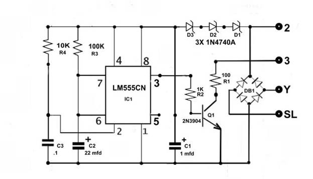
The core of the circuit is the voltage regulator, which steps up the voltage from the 1.5V battery to the required charging voltage for the phone, usually around 5V. Commonly used voltage regulators for this purpose include the LM7805 or a boost converter circuit that can efficiently increase the voltage while maintaining a stable output.
A charging controller is essential to manage the charging process, ensuring that the phone battery is charged safely and efficiently. This component monitors the voltage and current flowing into the phone, preventing overcharging, which can damage the phone's battery. The TP4056 is a popular choice for lithium-ion battery charging applications, providing integrated protection features.
The connection interface typically includes a USB output, allowing standard USB cables to be used for charging various phone models. Proper connectors and wiring should be employed to ensure a secure and reliable connection between the charger circuit and the phone.
In addition to the primary components, it is advisable to include capacitors for smoothing the output voltage and filtering any noise that may affect charging performance. A diode may also be included to prevent reverse current flow, protecting the battery and the circuit from potential damage.
Overall, this cell phone charger circuit provides an effective solution for charging mobile devices in situations where conventional mains power is unavailable, making it a valuable tool for emergency situations or outdoor activities.Use this cell phone charger circuit and a 1.5V battery when you do not have main power and need to charge your phone 🔗 External reference
Related Circuits
This application note outlines the functionality of the MAX4929E, which manages the switching of all low-frequency signals (LoF) required for a 2:1 HDMI/DVI switch while providing high-level ESD protection for all external lines. It also details how the MAX4929E...
Several weeks ago, a situation arose where there were no telephones left to restore. All payphone projects had been completed and were now collecting dust on shelves. A desire emerged to create a unique, creative, and useful project for...
The requirement was to add a digital readout to a manually operated bend roller machine to accurately monitor the amount of material fed into the machine. The readout should be user-friendly, requiring no setup other than initial calibration, and...
This simple circuit will find many applications as a battery eliminator for low power requirements. It consists of a transformer, a bridge rectifier and an electrolytic capacitor followed by a zener controlled series pass transistor. The output is stabilized...
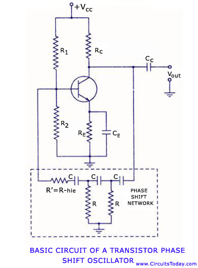
Transistor RC phase shift oscillator. RC phase shift oscillator using operational amplifier. RC phase shift network. Theory and working principle. Circuit diagram. The transistor RC phase shift oscillator is a type of electronic oscillator that generates sine wave signals. This...
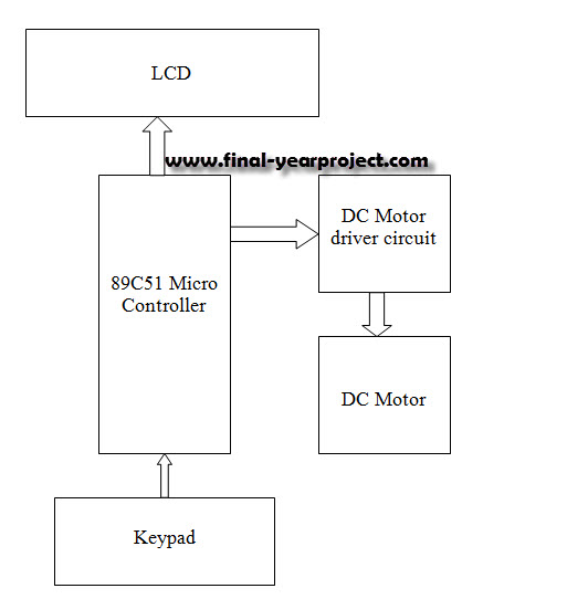
This report details an electronic project focused on the speed control of a DC motor using a microcontroller and PWM (Pulse Width Modulation). The system integrates a microcontroller with an LCD, keypad, and a DC motor driver. The microcontroller...