
1 KW Power (Watt) Meter
 Meter")
This wattmeter circuit is designed to accurately measure electrical power in a range of up to 1 kW, making it suitable for various applications where power consumption needs to be monitored. The circuit operates effectively within a voltage range of 117 Vac ±50 Vac, which allows for flexibility in usage. It is particularly notable for its simplicity, utilizing a single transistor to achieve the desired measurement functionality.
The circuit is engineered to measure power only during negative cycles, which may limit its application in certain scenarios but ensures that it captures the relevant data for specific load types. The absence of an external power supply is a significant advantage, as this feature enhances portability and ease of use. The circuit's idle power consumption is minimal, drawing only 0.5 W, which is beneficial for energy efficiency.
In terms of performance, the circuit has a load current sensing voltage of 10 mV, indicating its sensitivity to small variations in current. Additionally, it exhibits a load voltage loss of just 0.01%, highlighting its efficiency in power measurement. The circuit excels in rejecting reactive load currents, with a rejection ratio exceeding 100:1 for linear loads. This characteristic is crucial for accurate power measurement, as it minimizes the influence of reactive components in the load.
The nonlinearity of the circuit is approximately 1% of full scale when using a 50 A meter movement, which is acceptable for many practical applications. To further enhance accuracy, a copper shunt can be integrated into the design. This shunt compensates for temperature-induced variations in resistance, ensuring that the gain remains consistent across different operating conditions.
In summary, this wattmeter circuit represents a robust solution for measuring true power in various electrical applications. Its design emphasizes simplicity, efficiency, and accuracy, making it a valuable tool for both hobbyists and professionals in the field of electronics.This watt-meter circuit has measurement range up to 1-KW. This circuit can give the complete (X)(Y) function although uses only one transistor. Actually, this circuit is used for 117 Vac ±50 Vac operation. For lower or lower voltage, this circuit can be modified easily. This circuit only measure power on negative cycles. The advantages of this cir cuit is this circuit does not need external power supply. This circuit measures true power that is delivered to the load. Here is the schematic diagram of the circuit:At idle section, this circuit draw only 0. 5W. This circuit has load current-sensing voltage of 10mV and load voltage loss of 0. 01%. For linear loads, Rejection of reactive load currents is better than 100:1. When using a 50- A meter movement, the nonlinearity of this circuit is about 1% full scale. Copper shunt can be used to give correct gain due to temperature. Be the first of your friends to get free diy electronics projects, circuits diagrams, hacks, mods, gadgets & gizmo automatically each time we publish. Your email address & privacy are safe with us ! 🔗 External reference
Related Circuits
USB Battery Charger for Lithium Ion batteries using the LM3622 is a specialized charger circuit designed to operate with power sourced from a USB connection. The current consumption of the LM3622 is limited to 400mA by a resistor (R1),...
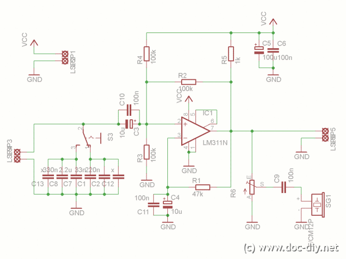
The input capacitor is used for low-frequency cut-off, with a standard value of 0.1 µF, resulting in a cut-off frequency of approximately 16 Hz. The input capacitor plays a crucial role in filtering unwanted low-frequency signals in electronic circuits. By...
This article explains the process of constructing a basic inductance meter. The printed circuit board (PCB) layout is provided. The construction of a simple inductance meter involves several key components and a well-designed PCB layout to ensure accurate measurements of...
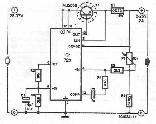
A simple variable power supply circuit can be designed using the LM723 regulator, which provides a maximum current of up to 2A and a variable voltage range between 2 and 25 volts. The LM723 voltage regulator is an integrated circuit...
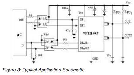
An integrated solution for two output channels that simplifies design and enhances reliability. The device, the VNI2140J, integrates on-chip two 45V Power MOSFET channels with a typical Rds(on) of 80mOhm at 25 degrees Celsius. The VNI2140J is a highly integrated...
The circuit shown demonstrates how to power one or two LEDs from a 120-volt AC line by utilizing a capacitor to reduce the voltage and a small resistor to limit the inrush current. Because the capacitor needs to conduct...