
ac line powered leds

The circuit operates by harnessing the alternating current (AC) supply, which oscillates between positive and negative voltages. The capacitor serves as a reactance component that drops the AC voltage to a level suitable for the LEDs, which typically operate at much lower voltages. The resistor is crucial for limiting the inrush current when the circuit is first powered on, preventing potential damage to the LEDs.
The diode connected in parallel with the LED ensures that during the negative half cycle of the AC waveform, the current has a path to flow, thus preventing reverse voltage from damaging the LED. This configuration is essential as standard LEDs are polarized components that only allow current to flow in one direction. The use of a second LED in reverse orientation can provide a similar protective function while also allowing for the visual indication of the AC signal through alternating illumination.
A tri-color LED can also be utilized in this arrangement. When connected to an AC source, it can illuminate in different colors depending on the phase of the AC cycle. In this specific setup, the tri-color LED would appear orange due to the combination of red and green light emitted during the alternating cycles.
Overall, this circuit design is efficient for low-power applications where simple visual indicators are required without the need for complex power supply circuits. It is particularly useful in applications such as indicator lights, decorative lighting, or simple visual alarms, where the simplicity and low cost of the components are advantageous. Proper consideration should be given to the component ratings, ensuring that the capacitor and resistor can handle the AC voltage and current levels safely.The circuit below illustrates powering a LED (or two) from the 120 volt AC line using a capacitor to drop the voltage and a small resistor to limit the inrush current. Since the capacitor must pass current in both directions, a small diode is connected in parallel with the LED to provide a path for the negative half cycle and also to limit the reverse voltage across the LED.
A second LED with the polarity reversed may be subsituted for the diode, or a tri-color LED could be used which would appear orange with alternating current.. 🔗 External reference
Related Circuits
This is a rather unusual QRP Power Amplifier design, with a wide frequency response; within three dB's from 300KHz to 30MHz. Overall gain is in the region of 16dB and the final output power may be well over four...

This simple circuit can be used to program the PIC16F84 and similar flash memory type components. It utilizes a 555 timer integrated circuit (IC) to generate the programming voltage from a +5V power supply, enabling operation from a computer's...

The Videowire converts a baseband video signal into a low impedance differential signal that can be sent over ordinary four conductor telephone wire. A send board mounted close to the camera generates the differential signal and a receive board...
In the circuit below, a quad voltage comparator (LM339) is used as a simple bar graph meter to indicate the charge condition of a 12 volt, lead acid battery. A 5 volt reference voltage is connected to each of...
This circuit uses a germanium diode (marked Ge) as a temperature sensor. I used an OA90 diode but others should do. The 'ring' of Tr1 and Tr2 bias each other. Tr1's collector current is stabilized by the 5v6 zener,...
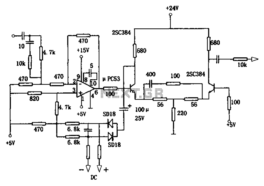
The circuit is designed for a broadband linear detection application with a bandwidth of 10 MHz. It serves as a millivoltmeter measuring instrument suitable for frequencies exceeding 10 MHz. The circuit features a linear detector utilizing operational amplifiers, specifically...