
1 transistor treasure locator circuit

PARTS LIST:
- B1 — 9-Vdc transistor battery
- C1 — 365-pF trimmer or variable capacitor
- C2 — 100-pF, 100-V silver mica capacitor
- C3 — 0.05-µF disc capacitor
- C4 — 4.7- or 5-µF, 12-V electrolytic capacitor
- L1 — Search coil consisting of 18 turns of #22 enamel wire, scrambled wound on a 4-inch diameter form
- Q1 — RCA SK3011 npn transistor or equivalent
- R1 — 680-ohm, 1/2-watt resistor
- R2 — 10,000-ohm, 1/2-watt resistor
- R3 — 47,000-ohm, 1/2-watt resistor
The described locator circuit functions as a metal detector, leveraging the principles of inductance and oscillation. The core component of the system is the search coil, L1, which is intricately wound to create a specific inductance value. This inductance is crucial as it interacts with the oscillator circuit to produce a frequency that can be detected by the radio.
The oscillator circuit is comprised of the variable capacitor C1, which allows for fine-tuning of the oscillator frequency to match the detected signal frequency. The radio serves as an auditory output device, providing feedback through changes in tone when metal is detected. The change in frequency occurs because the presence of metal alters the inductance of L1, leading to a shift in the oscillator's output.
The use of RTV adhesive to stabilize the search coil is a critical step in ensuring consistent performance. This adhesive prevents any mechanical movement that could lead to variations in inductance during operation, thereby enhancing the reliability of the locator.
The power supply is provided by a 9-Vdc transistor battery (B1), which powers the entire circuit. The remaining components, including the resistors R1, R2, and R3, serve to set the biasing and gain of the transistor Q1, which is central to the oscillator's operation. Capacitors C2 and C3 filter and stabilize the circuit, ensuring that it operates within the desired frequency range without unwanted noise.
In summary, this locator circuit integrates various electronic components to create a functional metal detection system, utilizing a combination of inductive principles and radio frequency detection to provide real-time feedback on the presence of metallic objects.Locator uses a transistor radio as the de-tector. With the radio tuned to a weak station, adjust Cl so the locator oscillator beats against the received signal. When the search head pas¬ses over metal, the inductance of LI changes thereby changing the locator oscillator's fre¬quency and changing the beat tone in the radio.
The search coil consists of 18 turns of #22 enameled wire scramble wound on a 4-in. diameter form. After the coil is wound and checked for proper operation, saturate the coil with RTV adhesive for stable operation of the locator. PARTS LIST : B1 — 9-Vdc transistor battery C1 —365-pF trimmer or variable capacitor C2—-100-pF, 100-V silver mica capacitor C3—0.05-/i.F, disc capacitor C4—4.7- or 5-^F, 12-V electrolytic capacitor L1—Search coil consisting of 18 turns of #22 enamel wire scramble wound on 4-in. diameter form Q1 — RCA SK3011 npn transistor or equiv. R1 —680-ohm, 1/2-watt resistor R2— 10,000-ohm, V2-watt resistor R3—47,000-ohm, 1/2-watt resistor
Related Circuits
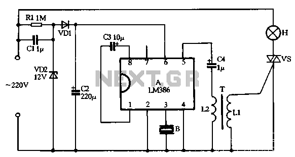
VD1, VD2, C1, and C2 comprise a simple half-wave rectifier capacitor step-down voltage regulator circuit, providing an output of approximately 12V for a linear power supply connected to the LM386. The LM386 is linked to the inverting input terminal...
This circuit is similar to the LED clock using 12 neon indicator lamps instead of LEDs. It operates from 2 high capacity ni-cad cells (2.5 volts) which keep it going for a couple weeks. High voltage (70 volts) for...

UPDATED 2014 This project presents the original high-power mobile phone jammer circuit, with all updates posted here. Caution is advised regarding the use of this device, as it is illegal. The purpose of sharing this circuit is solely for...
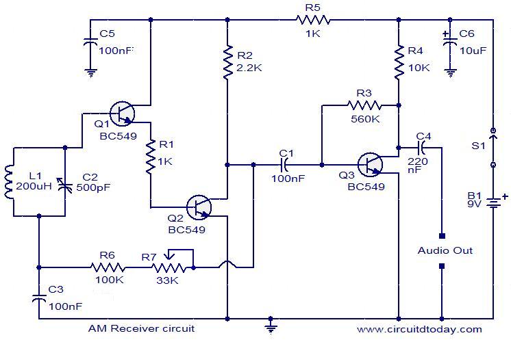
Circuit diagram of a modulator circuit in a transmitter and receiver of amplitude modulation. The modulator circuit in an amplitude modulation (AM) transmitter and receiver plays a crucial role in the process of encoding information onto a carrier wave. In...
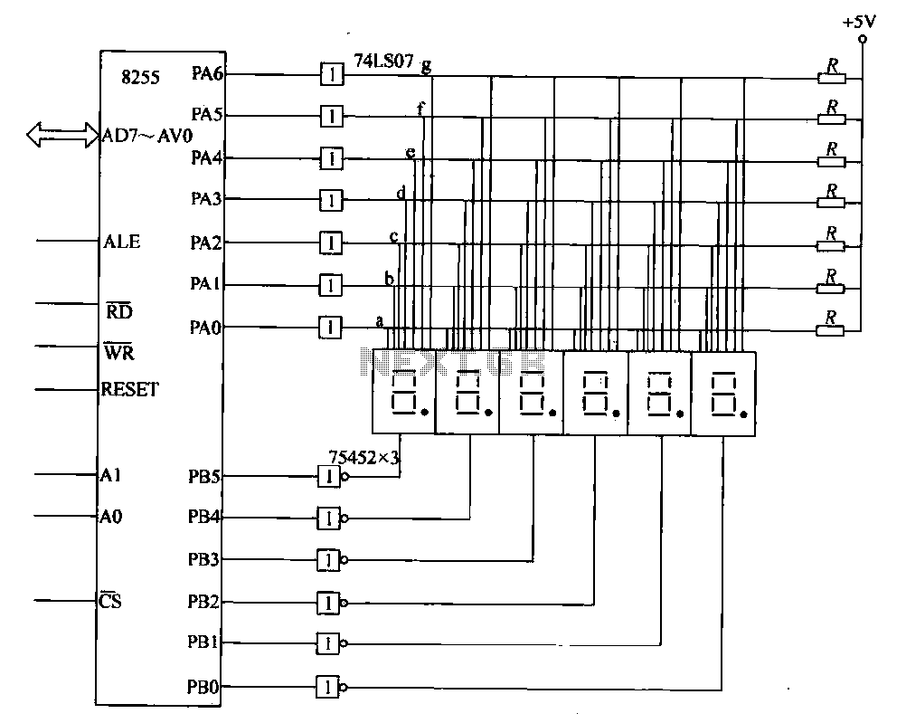
This circuit demonstrates a typical six-digit dynamic display configuration. It utilizes the PA 8255 for display output code and the PB port for bit selection code. The display buffer is designated as DISBUF, which processes the hexadecimal number obtained...

This circuit utilizes two quad op-amps to create an eight LED audio level meter. The op-amp employed in this circuit is the LM324, a widely used integrated circuit that is readily available from numerous electronic component suppliers. The 1K...