
6 digits dynamic display circuit

The circuit employs a PA 8255, which is a programmable peripheral interface that facilitates communication between microprocessors and peripheral devices. In this configuration, it manages the output for the display while the PB port is utilized for selecting specific bits that determine which segments of the display are activated. The hexadecimal numbers processed by the PA 8255 are essential for initializing the display, allowing for dynamic control of the visual output.
The 74LS07, a high-speed buffer/driver, amplifies the signals sent to the display, ensuring that the current supplied is sufficient to illuminate the LED segments effectively. This is crucial for maintaining visibility and performance, particularly in applications where the display may be subjected to varying ambient light conditions.
The use of a 75452 buffer/inverting driver enhances the circuit's capability to manage multiple display outputs. Each 75452 can handle two inputs, and since three are required to drive the six displays, this configuration allows for efficient signal management and distribution. The bit selection process is vital for ensuring that only the intended segments of the display are activated at any given time, thereby creating a clear and coherent visual output.
Overall, this circuit exemplifies a robust design for dynamic LED displays, utilizing well-established components to achieve effective results in digital representation. The method of cycling through the digits rapidly is a standard technique in multiplexing, allowing for the perception of simultaneous illumination of all six digits by the human eye.Shows - typical of six dynamic display circuit. In the figure, the PA 8255 end date display output code. PB port output bit election code. Let the display buffer is DISBUF, then complete the number (hexadecimal) to be taken after 8255 to initialize a display, using software decoding method determined to be 7-segment display control corresponding to the number displayed by the team and then port the code j output, and after 74LS07 drive to enlarge the display of data on each bus. In the end what a digital display, depending on the location of the election code. Only bit line select signal corresponding PB port after the drive goes low, the corresponding bit will not be emitting display.
If you are displayed in order from left to right, each successive digital display period of time (such as Ims), after the last digit is displayed, then repeat the process, so that the human eye can see is the 6-digit "simultaneously" display. Wherein 74LS07 to six drives, which raise the LED drive current for certain. 8255: As a 74LS07 only six drives, so the 7-segment requires two 74LS07 driving after PB port 75452 via buffer / inverting drive, 'as a bit selection signal.
A 75452 includes two internal buffers / drivers, each buffer red / driver has two inputs. Drive six LED display requires 3 75452.
Related Circuits
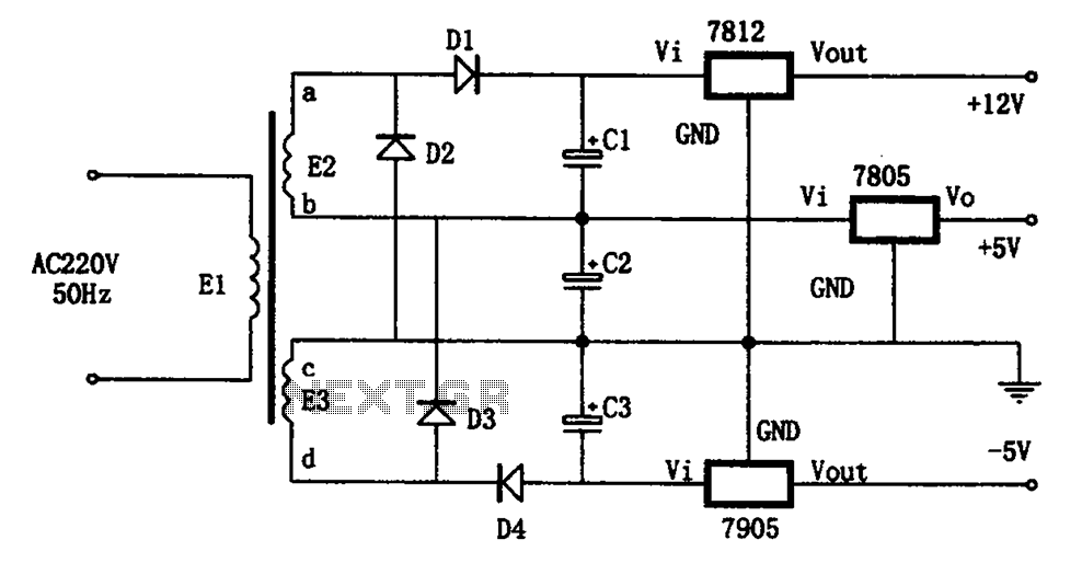
The circuit illustrated in the figure represents a specialized power supply configuration. It is straightforward in design and can be constructed using two identical secondary windings to generate three distinct DC voltage outputs: +5V, -5V, and +12V. The circuit...
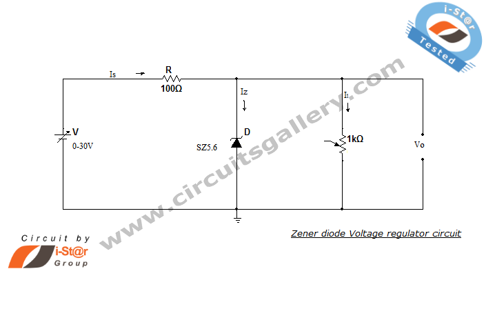
A Zener diode regulator is a fundamental electronic circuit valuable for hobbyists. This circuit provides a regulated output voltage, suitable for biasing other circuit components. The Zener diode operates in the reverse breakdown region, maintaining a nearly constant voltage...
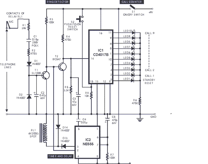
This circuit is designed to support nine independent telephones using a single telephone line pair, allowing for operation at nine different locations. It includes a bidirectional telephone line simulator that does not require actual telephone lines, enabling the coupling,...
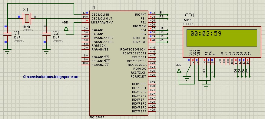
This tutorial on the PIC16F877 microcontroller addresses the question, "How to implement a digital clock using the PIC16F877?" The use of the PIC16 simulator (Proteus) is included. The PIC16F877 microcontroller is a versatile and widely used component in embedded systems,...
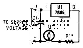
A 7805 can be configured as a constant-current regulator to function as an inrush current limiter. Resistor R1 will maintain a voltage of 5 V across it at all times, resulting in a total current through R1 of 5...
Six timing positions suited to different skin types; timing affected by sunlight intensity. This timer was designed for individuals seeking to achieve a tan. The electronic timer circuit described is intended for use in tanning applications, specifically designed to cater...