
10 12 14 15 16V DC to 18 22 26 28 30V DC Converter Circuit

The DC to DC converter operates on the principle of boosting the input voltage to a higher output voltage, making it particularly beneficial in applications where the available voltage from a source, such as solar batteries, is insufficient for the intended load. The converter typically employs a switching regulator topology, which efficiently transfers energy by rapidly switching the input voltage on and off.
Key components in this converter include an inductor, a switch (usually a transistor), a diode, and a capacitor. When the switch is closed, current flows through the inductor, storing energy in its magnetic field. When the switch opens, the inductor releases its stored energy through the diode to the output capacitor, thereby increasing the voltage. The output voltage can be adjusted by varying the duty cycle of the switching signal, which controls the ratio of the time the switch is on versus off.
This type of converter is particularly advantageous in renewable energy systems, where maximizing the energy harvested from solar panels is critical. By boosting the voltage, the converter enables better compatibility with various loads and energy storage systems, ensuring that the energy generated by the solar panels is utilized effectively.
Overall, the design of a DC to DC converter must consider factors such as efficiency, thermal management, and component ratings to ensure reliable operation under varying load conditions.This dc to dc converter raise a dc voltage at almost a double value and is useful for raising the output voltage of solar batteries up to the required leve.. 🔗 External reference
Related Circuits
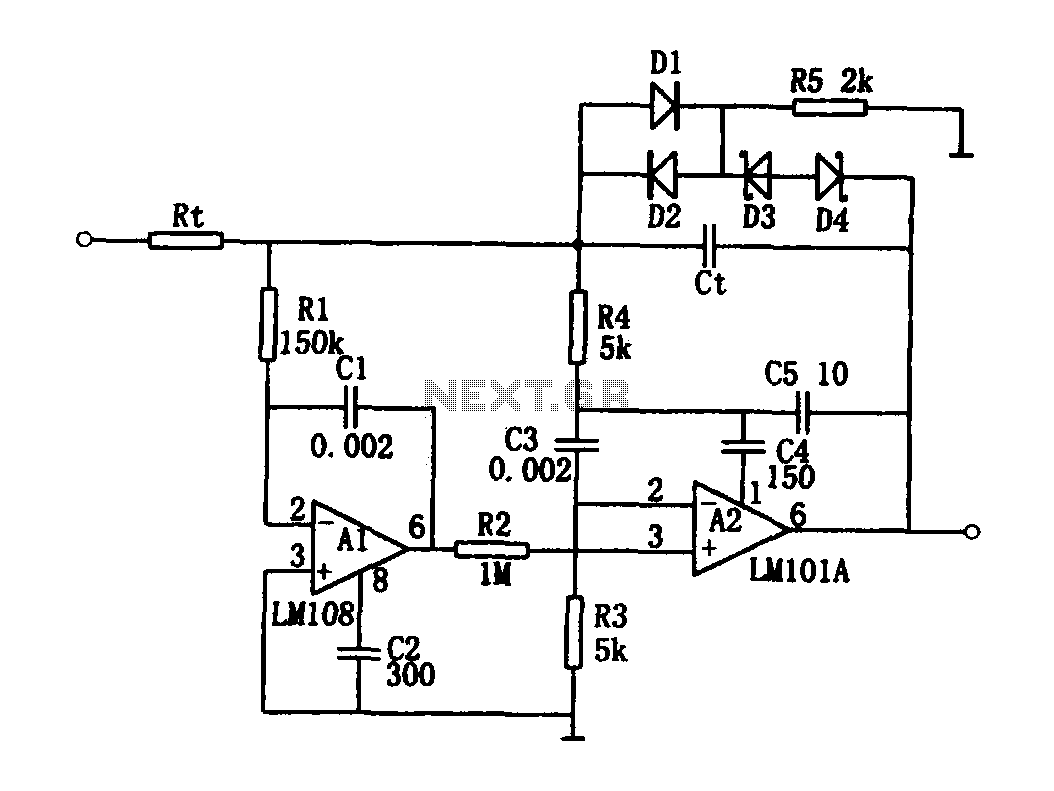
The high-speed integrating circuit is designed with an integration time constant circuit, RtCt, which offers a wide range. When the integrating capacitor Ct is not considered, A2 functions as a positive feedback compensation broadband AC amplifier. The negative feedback...
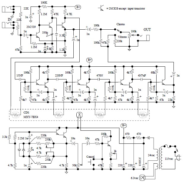
The Univibe is a footpedal-operated phaser or phase shifter designed to generate chorus and vibrato simulations for electric organs or guitars. It was introduced in the 1960s by Shin-ei, with the intention of emulating the "Doppler sound" characteristic of...
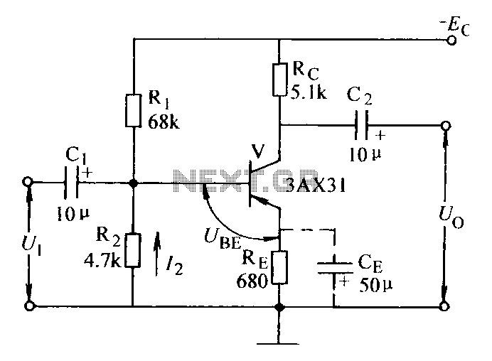
Current negative feedback voltage divider biased circuit diagram. The current negative feedback voltage divider biased circuit is a configuration commonly used in electronic amplifiers to stabilize the operating point and improve linearity. This circuit typically consists of an amplifier, a...
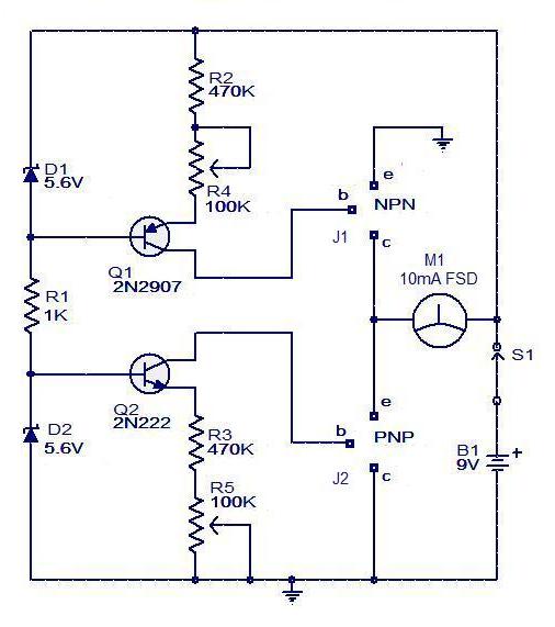
The circuit for a transistor tester is a relatively simple device. The transistor tester circuit illustrated below can be utilized to measure and identify the pins of a transistor, as well as determine its condition. Furthermore, this circuit can...
Figure 1 illustrates the VFO oscillator circuit operating within the frequency range of 10.58 to 10.74 MHz. This circuit is a redesigned version of a previously presented Colpitts oscillator, with a clearer representation. The inductor, labeled "L," has an...
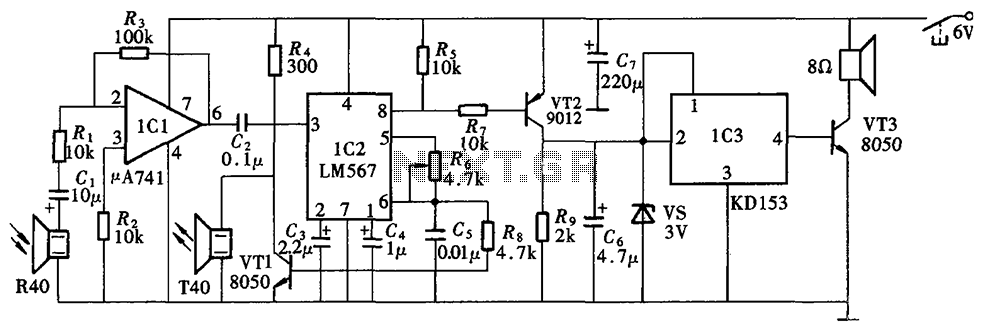
The Blind Pathfinder circuit primarily consists of the A741 operational amplifier, LM567 phase-locked loop, KD153 transistor, 8050 transistor, 9012 transistor, and various other components. The Blind Pathfinder circuit is designed to assist in navigation and obstacle detection, typically utilized in...