
10.58 to 10.74 mhz vfo oscillator circuit

The VFO oscillator circuit is a critical component in various applications, including communication systems and signal processing. The Colpitts oscillator configuration is particularly favored for its stability and ease of tuning. The choice of components, such as the T50-6 core inductor and the specific capacitor types, is essential for achieving the desired performance characteristics. The inductance and capacitance must be carefully selected to ensure that the resonant frequency falls within the specified range of 10.58 to 10.74 MHz.
In practical implementations, the layout of the circuit can significantly impact performance, particularly in high-frequency applications. Stray inductance and capacitance can alter the expected resonant frequency, necessitating careful circuit board design and component placement to minimize these effects. Additionally, the use of high-quality capacitors, such as Silvered Mica or COG types, is crucial for maintaining low losses and stable frequency performance.
The operational principles of resonant circuits should also be understood in the context of their application. For instance, in a parallel resonant circuit, the impedance at the resonant frequency is at a maximum, resulting in minimal current flow through the circuit at that frequency. In contrast, a series resonant circuit presents a minimum impedance at resonance, allowing maximum current flow. This behavior is exploited in various applications, including RF amplifiers and filters, where selective frequency response is required.
Designers must also consider the impact of temperature variations and component tolerances on the oscillator's frequency stability. Implementing temperature compensation techniques and utilizing components with tight tolerances can enhance the reliability of the VFO circuit in varying environmental conditions. Overall, a comprehensive understanding of the theoretical and practical aspects of resonant circuits is essential for engineers working on high-frequency oscillator designs.Figure 1 shows the 10. 58 to 10. 74 MHz VFO oscillator circuit. Yes, this is the same circuit that was presented last, but I`ve re-designed to show the Colpitts oscillator more clearly. "L" is approximately 1. 5 uh, 19 becomes a core T50-6 (yellow). The value of C6 is found experimentally. I 69 pF (47 pF to 22 pF and a parallel). More information abo ut this during check-out. "L" and the VVC with C6 form the parallel-tuned circuit that determines the frequency of the VFO. The CVV is a MV2104. Capacitors marked with an asterisk are required Silvered Mica, COG or NPO. You might wonder how the component values for the resonance circuit is determined. Well, when Jupiter aligns with Mars and Mercury on the cusp of the new moon, if the inductive reactance equals the capacitive reactance, then we have a resonance circuit. For a given frequency there are infinite combinations of L and C is a resonance circuit. Experience shows that the variable capacitors and VVC in the range of 5 to 300 pF pF are quite practical.
Combine this with the fact that UH 1. 5 coil and a capacitor of 150 pF resonate near the frequency of interest, and has the component values for the resonance circuit this VFO. You can find the formulas to calculate all this in your manual if you like to do arithmetic. The values of the components actually used in the circuit to take into account "stray" inductance and capacitance that occurs in the real world.
More information about this during check-out. Resonant circuits are fascinating creatures! Although I did not go into a theoretical discussion, there are some fundamental characteristics of resonant circuits that you (and me) should be considered in the construction of VFO, filters, amplifiers, etc. There are two types of resonant circuits commonly used are the series resonant circuit and parallel resonant circuits, as shown below.
Here are two important things to consider: Parallel resonant circuits reduce the flow of AC current in the resonant frequency (and pass all other frequencies) pass resonant series circuit of alternating current in the resonant frequency (and mitigate all the other frequencies). 🔗 External reference
Related Circuits
This is an enhanced infrared (IR) remote control extender circuit that exhibits high noise immunity, resistance to ambient and reflected light, and an extended operational range of approximately 7 meters between the remote control and the extender circuit. It...
The motor control circuit depicted in the image utilizes the LM339 comparator among other components. When the input control signal is high (PWL), comparators A and A3 activate the power amplifier circuit, which consists of A4, VT5, and VT6,...
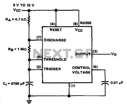
The NE555 timer is configured in astable mode and utilizes three timing components (RA, RB, and Ct). A 0.01 µF bypass capacitor is connected to pin 5 to enhance noise immunity. The operational limitations of the astable mode are...

This circuit operates effectively across a broad frequency spectrum. XTAL 1 serves as a fundamental-frequency crystal. Tl and CI are adjusted to match the input frequency. This circuit can be utilized as a straightforward shortwave converter for AM radios,...
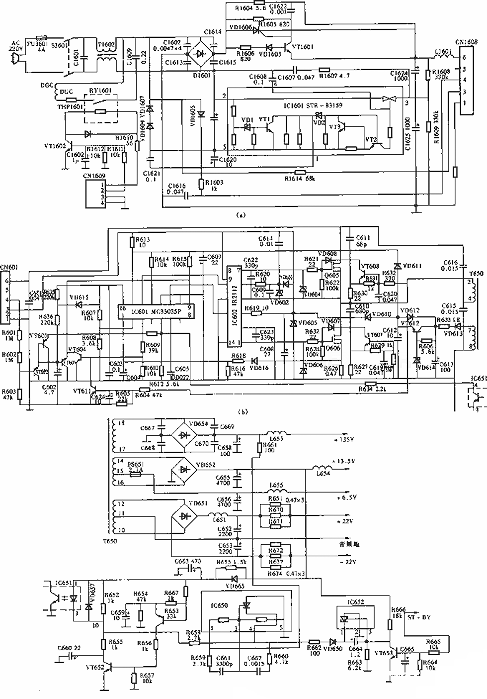
The circuit of the Sony KV-S29MHl (S Movement series) TV switching power supply (SIR a 80145A) consists of three main sections: (A) the power oscillation part, (B) the regulator part, and (C) the output section. The Sony KV-S29MHl TV switching...
The circuit above is a canonical AC coupled common emitter amplifier, which is typically used as a linear amplifier rather than a switch that activates when the input exceeds a certain level. The AC coupled common emitter amplifier is...