
10 Amp 13.8 Volt Power Supply

Power supplies are critical components in any amateur radio setup, providing the necessary voltage and current to operate transceivers and other equipment. A typical homemade power supply circuit includes several key components: a transformer, a rectifier, filtering capacitors, and a voltage regulator.
1. **Transformer**: The transformer is responsible for stepping down the AC voltage from the mains to a lower voltage suitable for the radio equipment. The selection of the transformer is crucial; it should have a suitable voltage rating and sufficient current capacity. For example, a transformer with a secondary voltage of 12V to 15V and a current rating of at least 5A is common for many amateur radio applications.
2. **Rectifier**: After the transformer, the AC voltage is fed into a rectifier, which converts the AC voltage to DC. A full-wave bridge rectifier configuration is often used for its efficiency, consisting of four diodes arranged to allow both halves of the AC waveform to contribute to the output. The diodes must be rated for the expected load current and reverse voltage.
3. **Filtering Capacitors**: The output from the rectifier is pulsating DC, which requires filtering to smooth out the voltage. Large electrolytic capacitors are typically used to reduce ripple voltage. The capacitance value depends on the load current and the desired ripple voltage; common values range from 1000µF to 10,000µF.
4. **Voltage Regulator**: To maintain a stable output voltage, especially under varying load conditions, a voltage regulator can be employed. Linear regulators like the LM7812 can be used for low power applications, while switching regulators may be necessary for higher power requirements due to their efficiency.
5. **Heat Sink**: A heat sink is essential for dissipating heat generated by the voltage regulator and other components, ensuring reliable operation.
6. **Protection Features**: Additional features such as fuses, thermal protection, and over-voltage protection circuits can be integrated to enhance safety and reliability.
Building a power supply provides practical experience and a deeper understanding of electronic components and circuit design. It is advisable to follow safety precautions, especially when working with high voltages and currents, and to ensure proper insulation and ventilation in the design.Sometimes amateurs like to home-brew their power supplies instead of purchasing one off the shelf at any of the major ham radio retail dealers. The advantage to rolling your own power supply is that it teaches us how they work and makes it easier to troubleshoot and repair other power supply units in the shack.
It should be noted that there is no real cost advantage to building your own power supply unless you can get a large power transformer and heat sink for a super low price. 🔗 External reference
Related Circuits
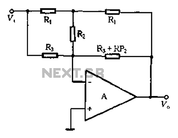
At high frequencies, the capacitor Cz can be considered a short circuit (i.e., the resistance of the RPi is negligible). This is illustrated in Figure 4-6 (a) of the apparatus, which corresponds to the equivalent circuit shown in Figure...
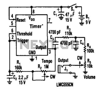
This metronome operates on a current of only 0.25 mA, making it suitable for battery-powered applications. It offers a tempo range from 34 to 246 beats per minute. The circuit can utilize a CMOS timer, such as the LM555...
A stereo valve phono preamplifier has been constructed by a technician. The device requires a power transformer and various components, excluding the valves, which the technician recommends sourcing based on individual needs. Experienced DIY enthusiasts are invited to share...

There are many applications where the accuracy of a digital or analog (bar graph) output is not necessary, but a solution that offers more than a simple low/high indicator is desirable. In various electronic applications, there exists a need for...
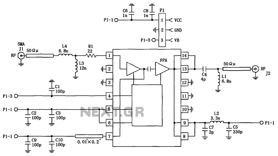
The circuit illustrated in FIG consists of the RF2103P 915MHz RF amplifier circuit. P1 serves as the outlet, where P1-1 connects to power Vcc, P1-2 connects to ground, and P1-3 is used for the power down control voltage VB....

Using inexpensive components, you can fit a simple probe circuit into a pencil-sized enclosure. When both LEDs are on, the probe indicates the presence of an ac voltage; either LED alone indicates the presence and polarity of a dc...