
Voltage Test Probe

The described probe circuit is a compact and efficient device designed to detect both alternating current (AC) and direct current (DC) voltages. The circuit utilizes a simple arrangement of components to achieve its functionality, making it suitable for a variety of applications in electrical testing.
The core of the circuit consists of a diode bridge, which is essential for converting AC voltage to a usable form for the LEDs. The diodes in the bridge configuration ensure that the circuit can handle the reverse voltage, providing the necessary peak-inverse voltage rating to protect against voltage spikes. This is particularly important in environments where the probe may encounter fluctuating voltages.
The circuit includes two light-emitting diodes (LEDs), which serve as visual indicators of voltage presence and polarity. When both LEDs are illuminated, it indicates that an AC voltage is present. In contrast, if only one LED lights up, it signifies the presence of a DC voltage, with the specific LED indicating the polarity of the voltage. This dual functionality allows the user to quickly ascertain the type of voltage being tested.
Resistors R1 and R2 are part of a current source configuration that helps to regulate the current flowing through the LEDs. The values of these resistors can be selected based on the desired brightness of the LEDs and the specific voltage range being tested.
Transistors Q1 and Q2 are employed to amplify the current from the diode bridge, ensuring that the LEDs receive sufficient current to illuminate brightly. The choice of transistors should be based on their current rating and response time to ensure reliable operation in the presence of varying input voltages.
To protect the circuit from transient voltage spikes, a spike-suppression network comprising resistor R3 and capacitor C1 is included. This network serves to absorb sudden voltage changes, thereby safeguarding the sensitive components, particularly the transistors, from damage due to excessive voltage.
Overall, this simple probe circuit is a practical solution for voltage detection, leveraging inexpensive components and a straightforward design to provide reliable performance in a compact form factor. The integration of visual indicators and protection mechanisms enhances its usability and longevity in various electrical testing scenarios.Using inexpensive components, you can fit a simple probe circuit into a pencil-sized enclosure. When both LEDs are on, the probe indicates the presence of an ac voltage; either LED alone indicates the presence and polarity of a dc voltage. The diode-bridge arrangement allows one-way current source R1, R2, Q1, and Q2 to light either LED (or both) when the probe is activated by a test voltage.
Diodes provide the necessary peak-inverse voltage rating; R3 and C1 provide a spike-suppression network to protect the current-source transistors. 🔗 External reference
Related Circuits
This circuit allows for the testing of quartz resonators within a frequency range of 32 kHz to 24 MHz. The operational status of the quartz resonator is indicated by a diode signaling an LED and an acoustic signal. The circuit...

As Ron suggests, controlling the output voltage from a regulator can be made variable in three ways. Using a fixed reference zener diode to increase the output by the value of the zener. A variable resistor for variable output,...
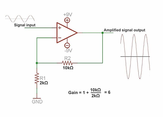
An amplifier is a device that increases the voltage in a circuit. The simplest type is an operational amplifier, and this video will demonstrate how these devices function and how to implement them in electronic applications. As an example,...

This voltage regulator and current limiter combination can be constructed using two 7805 regulators as illustrated. Resistors R1, R2, and R3 should be chosen to achieve a 5-V drop at the maximum allowable current limit. Switch S1 selects one...
In this circuit, an LM339 quad voltage comparator is utilized to generate a time delay and control a high current output at low voltage. Approximately 5 amps of current can be sourced using a pair of fresh alkaline D...
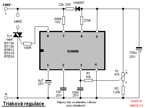
Triac regulation is designed to control the power of mains appliances. It can adjust the brightness of incandescent light bulbs, halogen lamps, dimmable energy savers, heaters, and other thermal devices, as well as regulate motors. The power can be...