
10 Band Graphic Equalizer

Each unit within this circuit shares common materials with the rest, with the only difference being the capacity of capacitors that form the filter in each unit. The position of the fader regulation runners, RV1 to RV10, determines the function of the unit. When the runner is centrally positioned, the filter does not intervene with the signal passing through it, and the gain of the particular unit is one [ X1 ].
However, if the runner is moved towards one side of the exit, the unit behaves as a cut-off filter for that specific range. This action results in the reduction or degradation of signals within the predetermined frequency range. Therefore, the circuit essentially functions as a frequency-specific amplifier or attenuator, depending on the position of the fader regulation runners.
The design and function of this graphic equalizer make it a flexible tool for modifying and customizing the output of audio signals. It allows the user to adjust the intensity of different frequency bands independently, thus providing a high degree of control over the sound profile. This is particularly useful in various audio applications such as music production, broadcasting, and sound reinforcement.The circuit of graphic equalizer, allocates ten adjusting potesometer , that each one from them affects in a predetermined area of frequencies, the central frequency of which abstains a octave (double), from the central frequencies of her neighbouring regions. Each unit has common materials with remainder and it differs only in the capacity of capacitors that constitutes the filter in each unit.
When the runner of fader regulation RV1 until RV10, is in the middle then we do not have no intervention of filter above in the signal that passes from in his and gain of particular unit, is one [ X1 ]. On the contrary if the runner is moved to a side of exit, the unit acts as filter of cutting off of area and it degrades the signals of predetermined area of frequencies.
🔗 External reference
Related Circuits
The CXA1821M is an integrated circuit designed for compact disc players. This IC includes an Automatic Power Control (APC) circuit along with RF, focus error, and tracking error amplifiers for 3-spot optical pickup output. It also supports voltage-converted optical...
The circuit utilizes two 2N3819 FETs arranged in a cascode configuration. The lower FET functions in common source mode, while the upper FET operates in common gate mode, achieving full high-frequency gain. The lower FET is tunable, enabling peak...
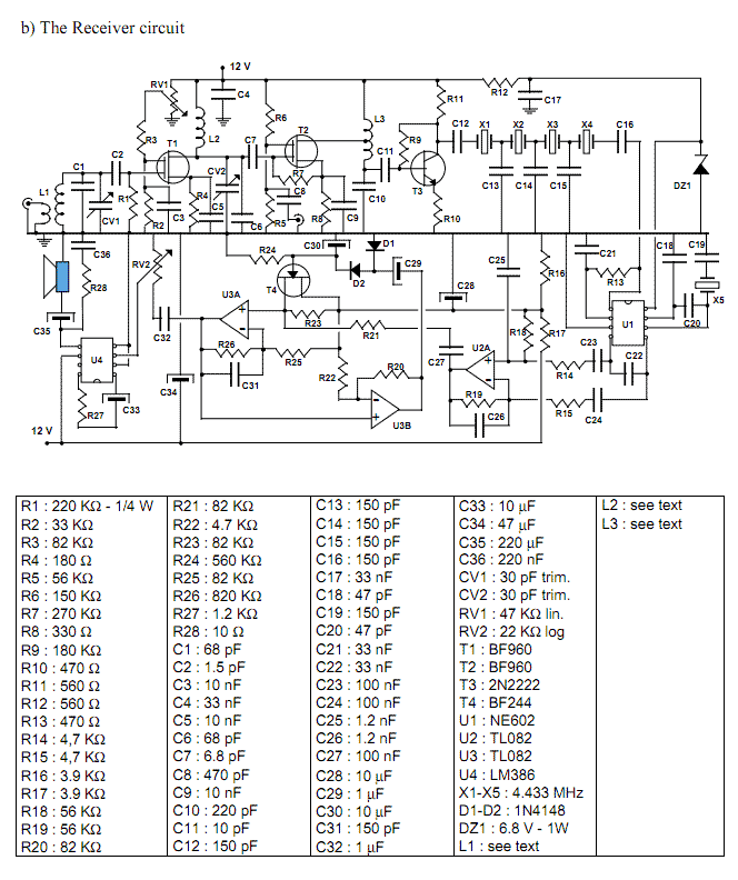
The transceiver is composed of three single-sided printed boards 100x70 mm; these may be stacked to reduce the overall size of the metal cabinet. It is suggested to employ small size components (1/4 W resistors, 2.5 mm capacitors) which...
This is a three-band equalizer circuit, specifically a tone control circuit that utilizes a single operational amplifier (op-amp) and features three adjustable frequency ranges: bass, midrange, and treble. The three-band equalizer circuit employs an operational amplifier to achieve tone control...
In general, the transceiver switches the 4-element 1500 ohm xtal BPF ends between the inputs and outputs of the two SA602s to reverse the signal flow for R/T operation. Since no IF amplifier is used in the design, 20...
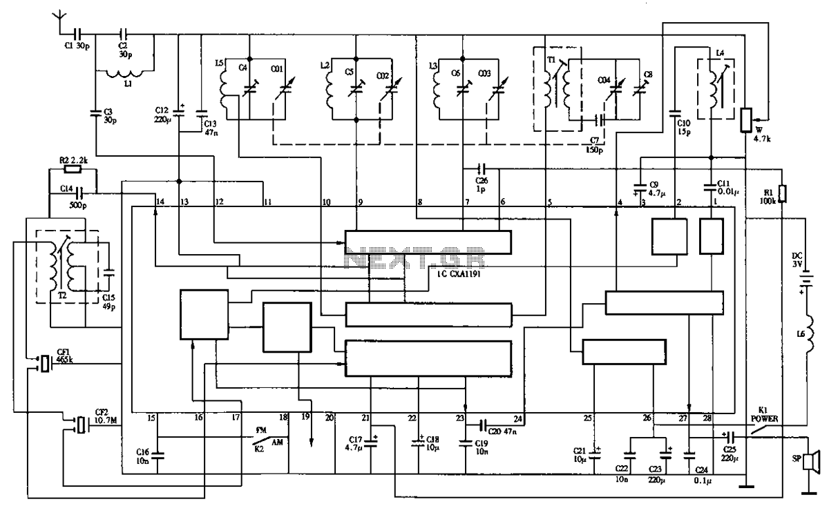
The circuit diagram of the Desheng R-202T type two-band radio is as follows. The Desheng R-202T is a two-band radio receiver designed to operate on both AM and FM frequencies. The circuit typically includes several key components that facilitate the...