
10 Dancing LEDs ElectronicCircuit Based On The LM358 IC

The Dancing LEDs circuit utilizes the LM358 operational amplifier to create a visually appealing light display. The circuit typically consists of multiple LEDs connected in parallel, which are driven by a modulated signal generated by the LM358. The operational amplifier is configured in a non-inverting amplifier arrangement, where the input signal is fed into one of its input terminals, and the output drives the LEDs.
The circuit may include additional components such as resistors, capacitors, and possibly a potentiometer to adjust the brightness or the speed of the LED modulation. The resistors limit the current flowing through the LEDs, ensuring they operate within their specified ratings to prevent damage. Capacitors may be used to filter the input signal or to create a time delay, which can add to the dynamic effect of the lighting.
To enhance the visual effect, the circuit can be designed to alternate the LEDs in a sequence, creating the appearance of dancing lights. This can be achieved by introducing a timing circuit using a 555 timer or similar component, which can provide a pulse-width modulation (PWM) signal to control the brightness and flashing rate of the LEDs.
Overall, the Dancing LEDs circuit based on the LM358 is an engaging project that combines basic electronic components to produce a captivating light display, suitable for decorative purposes or educational demonstrations in electronic principles.The following circuit shows about 10 Dancing LEDs Electronic Circuit Diagram. This circuit based on the LM358 IC. Features: IC1A amplifies about .. 🔗 External reference
Related Circuits

The following circuit illustrates a Stepper Motor Controller Circuit Diagram. This circuit is based on the 7404 IC. Features include a simple stepper motor. The stepper motor controller circuit utilizing the 7404 IC is designed to drive a stepper motor...
The Atmel Flash devices are ideal for developing, since they can be reprogrammed easy and fast. If you need more code space for your application, particularly for developing 89Cxx projects with C language. Atmel offers a broad range of...

The circuit diagram of a stereo PLL FM transmitter based on the BH1417 chip is presented. This recent design from RHOM integrates numerous capabilities within a compact package. It features pre-emphasis and a limiter to maintain consistent audio levels...

This simple and inexpensive yet powerful square wave oscillator can provide oscillation for any MOSFET-based inverter or UPS. The circuit features a central integrated circuit (IC), specifically the CD4047, with the HCF4047BE model from ST Microelectronics utilized. This design...

This circuit diagram illustrates a linear FM booster and RF amplifier utilizing the Philips 2N4427 transistor. The RF amplifier is designed to enhance the performance of small FM transmitters and bugs, employing two Philips 2N4427 transistors, delivering approximately 1...
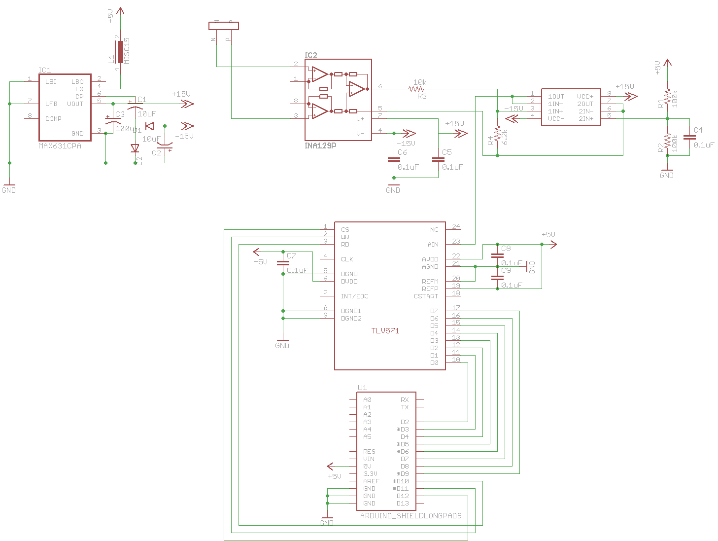
A digital oscilloscope is being developed using Arduino, designed as an Arduino Shield. The current implementation functions but exhibits signal distortions. A TLV571 chip is utilized in the design. The project involves creating a digital oscilloscope that can be mounted...