
stereo pll fm transmitter based bh1417
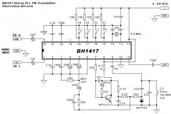
To create a PCB for this transmitter, utilize PCB design software like Eagle. Print the design on photo or glossy paper using a laser printer. Adhere the printed design to the copper side of the PCB and apply heat with a hot iron plate, allowing the ink to transfer onto the PCB, which will then be ready for the etching process. If a laser printer is unavailable, the design can be printed on standard paper and copied onto glossy paper at a local copy service.The circuit diagram of stereo PLL FM transmitter based BH1417 chip. This is certainly the most recent BH1417 FM Transmitter design diagram from RHOM that consists of lots of capabilities in a single tiny package. It includes pre-emphasis, limiter to ensure that the music can be transmitted at the same audio level, stereo encoder for stereo tr
ansmission, low pass filter that blocks any audio signals above 15KHz to avoid any RF interference, PLL circuit that delivers rock solid frequency transmission (no extra frequency drift), FM oscillator and RF output buffer. There is certainly 14 possible transmission frequencies with 200KHz increments that you can select using a 4-DIP switch.
Lower band frequencies begin from 88. 7 up to 89. 9 MHz, and upper band frequencies begin from 107. 7 up to 108. 9 MHz. BH1417 could be supplied with 4 - 6 voltage and needs only about 30mA, giving 20mW output RF power. BH1417 delivers 40dB channel separation that is fairly good, although older BA1404 FM Transmitter chip delivers slightly better 45dB channel separation. BH1417 is only offered in SOP22 IC case so this may possibly be an inconvenience for some people. On the other hand, since the chip is smaller than common DIP-based ICs it`s possible to fit the whole transmitter on a compact PCB.
BH1417 chip may possibly also be applied a stand alone stereo encoder. The benefit of that`s that you have full freedom of working with a transmitter and amplifier of your choice. You will still have a pre-emphasis, limiter, stereo encoder and low pass filter in a single tiny package since very few external components are required for these blocks.
PIN 5 is MPX output that could be directly connected to an external FM transmitter through a 10uF capacitor. Detailed information about this circuit, visit:. The kit of stereo PLL FM transmitter based BH1417 also available there. Make a PCB in very easy steps. ! Create your PCB design using PCB designer software like Eagle, print out your design on photo paper or glossy paper with laserjet printer.
Stick the printed design on the PCB (copper side) and then heat it using hot iron plate. The ink will stick on the PCB and it will be ready for etching process. Note: If you don`t have laserjet printer, then you can print the design on standard paper. Copy the printed design at Copy Service around your location (with glossy paper). 🔗 External reference
Related Circuits
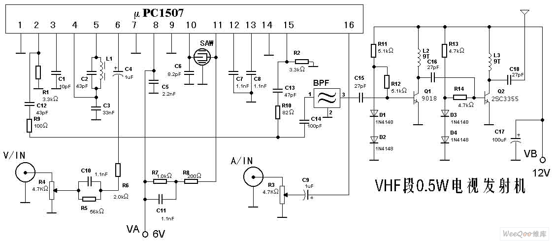
The TV transmitter described here is capable of transmitting audio and video signals from satellite television receivers, VCD players, and video recorders through an open circuit. It can also receive signals using open antennas. This device is ideal for...
If the audio input is a microphone, it is expected to precede an amplifier to achieve an output power of approximately 8W. The amateur seeking to enhance a small transmitter, which is likely already constructed, can utilize this circuit,...
Circuit Overview Many families now own various electronic devices such as televisions, VCD players, video recorders, game consoles, cameras, and DVDs. This circuit involves an RF signal repeater designed to work with a television signal transmitter, covering a radius...
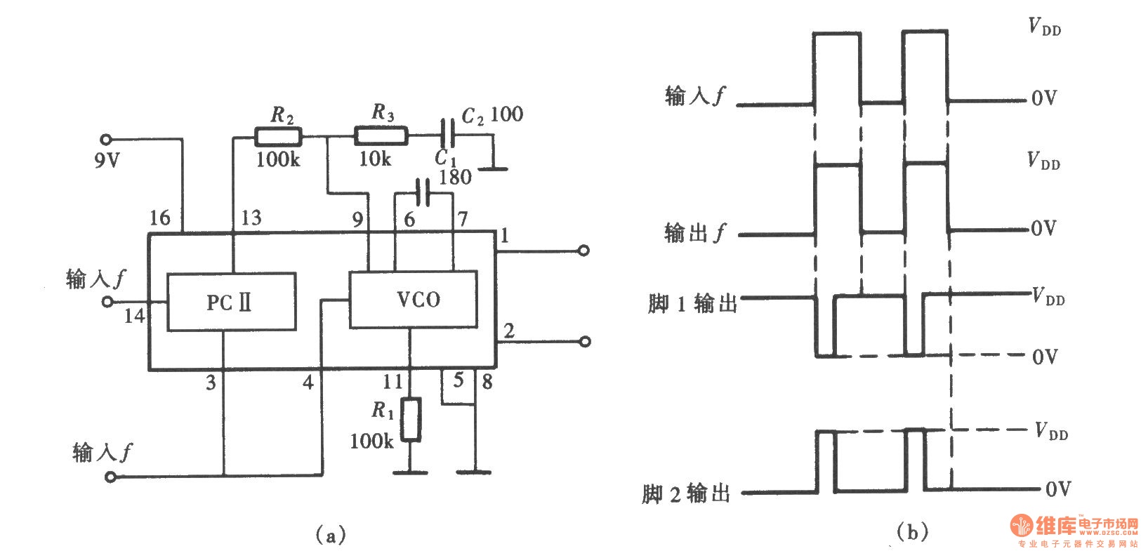
A frequency signal tracking circuit is implemented using a phase-locked loop (PLL) configuration, which is a fundamental application of the CD4046 integrated circuit. The circuit, illustrated in the accompanying chart, utilizes the CD4046 to form a PLL that effectively...
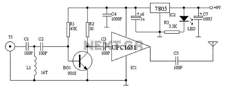
Operating radio transmitters without a license is illegal in most countries, so caution is advised with transmitter circuits. This FM low-power circuit is designed to operate within the 87-108 MHz band II, providing a range of approximately 20 to...
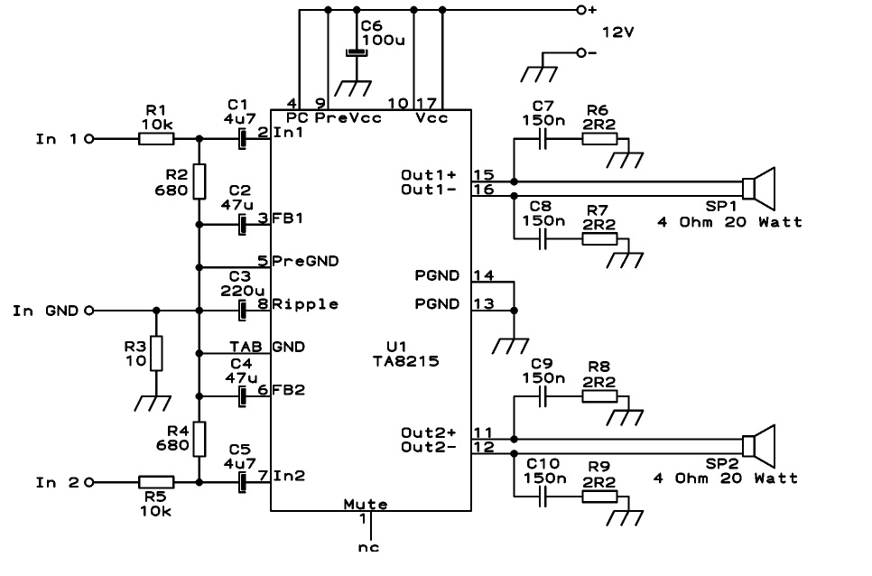
This circuit is designed as a stereo BTL (Bridge-Tied Load) 15W audio power amplifier using the TA8215 integrated circuit developed by Toshiba. Two TA8215 ICs are utilized in this configuration to achieve four output channels, with each IC providing...