
Hartley oscillator requires no coupled inductors

The Hartley oscillator is a type of LC oscillator that utilizes a tapped inductor, which is a key characteristic that differentiates it from other oscillator configurations. The circuit typically comprises a transistor or operational amplifier, a tapped inductor, and capacitors that form a feedback loop. The frequency of oscillation (f) can be determined using the formula:
\[ f = \frac{1}{2\pi\sqrt{L_{total}C}} \]
where \( L_{total} \) is the total inductance of the inductor, and \( C \) is the capacitance in the circuit. The tapped inductor provides the necessary feedback to sustain oscillations by allowing a portion of the output signal to be fed back into the input, which is crucial for maintaining the oscillatory behavior.
In designing a Hartley oscillator, the total inductance can be calculated, but determining the coupling coefficient, \( k \), can be challenging. The coupling coefficient is a measure of how effectively the magnetic fields of the inductors interact. A higher \( k \) value indicates stronger coupling, which can lead to more stable oscillations. However, achieving the desired \( k \) may require adjustments and empirical testing, often referred to as the "cut-and-try" method, where different configurations are tested until optimal performance is achieved.
The alternative equivalent circuit proposed in this design idea allows for modeling the Hartley oscillator's behavior before physical construction. This modeling can simplify the design process by enabling the engineer to simulate various parameters, including the effects of different inductance values and coupling coefficients. By using simulation software, one can visualize the frequency response and stability of the oscillator, making it easier to refine the design and identify potential issues early in the development process.
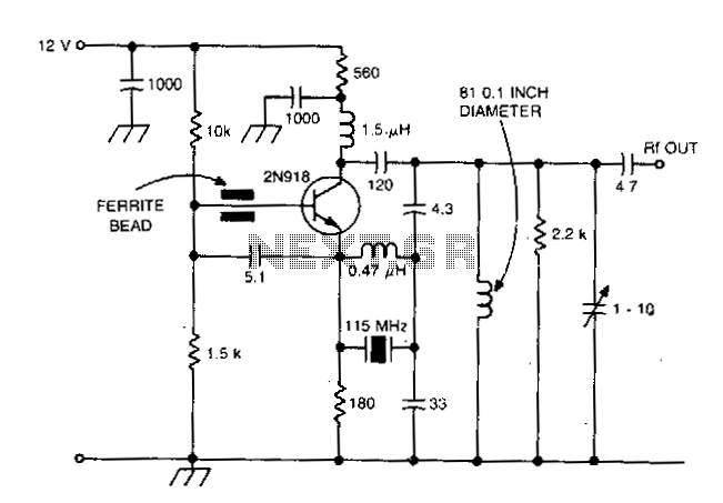
In summary, the Hartley oscillator is a versatile circuit that relies on a tapped inductor for feedback and frequency determination. Understanding the relationships between inductance, capacitance, and coupling coefficient is essential for effective design, and utilizing equivalent circuit models can facilitate the optimization process prior to prototyping.Examine a traditional Hartley oscillator circuit, and you`ll note its trademark: a tapped inductor that determines the frequency of oscillation and provides oscillation-sustaining feedback. Although you can easily calculate the total inductance required for a given frequency, finding the coupling coefficient, k, poses technical difficulties and may require experimental optimization, also referred to as the "cut-and-try" method.
This Design Idea presents an alternative equivalent circuit that allows you to model the circuit before building the prototype. 🔗 External reference
Related Circuits

The Wien-bridge oscillator is a distinctive circuit that produces an oscillatory output signal without requiring a sinusoidal input source. Instead, it utilizes capacitors with initial voltages to generate the output. This circuit can be particularly beneficial when connected to...
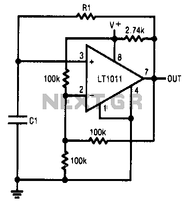
This simple RC oscillator utilizes a medium-speed comparator with hysteresis and feedback through R1 and C1 as timing elements. The frequency of oscillation is theoretically independent of the power supply voltage. Additionally, the comparator swings to the supply rails...
This circuit eliminates the traditional tungsten filament lamp amplitude regulator along with its associated time constant and linearity issues. Additionally, it addresses the reliability problems commonly found with lamps. The Wien Bridge oscillator is utilized, leveraging the fact that...
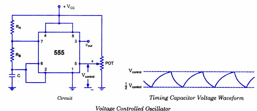
As discussed in previous blog posts, the pin 5 terminal serves as a voltage control terminal, allowing for the adjustment of threshold and trigger levels. Typically, the control voltage is set at +2/3VCC due to the internal voltage divider....
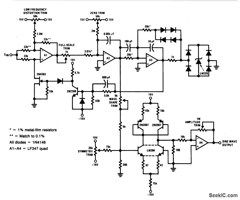
For a 0- to 10-V input, this circuit generates sine-wave outputs ranging from 1 Hz to 20 kHz, achieving linearity better than 0.2%. The distortion level is approximately 0.4%, and both the frequency and amplitude of the sine-wave output...
This design is intended for high reliability across a broad temperature range utilizing fifth and seventh overtone crystals. The inductor connected in parallel with the crystal induces antiresonance of crystal capacitance (Co) to reduce loading effects. This technique is...