
Temperature Logger and Standalone Voltage Logger
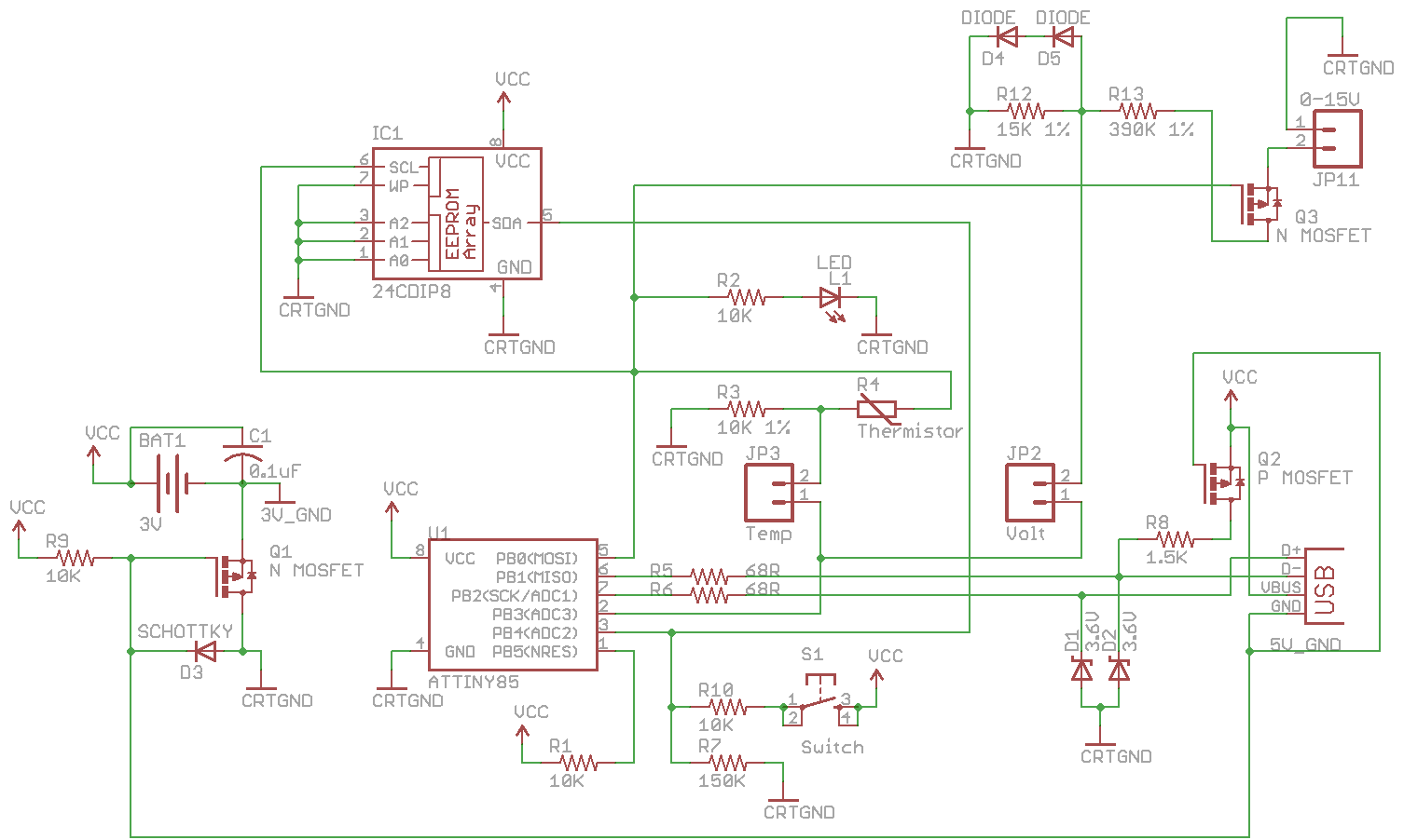
The combined SATL and SAVL circuit schematic integrates a voltage sensing circuit with a MOSFET to optimize power consumption. The MOSFET acts as a switch, allowing power to be drawn from the voltage source only when necessary, enhancing the overall efficiency of the design. The inclusion of two jumpers, Temp and Volt, provides flexibility in operation, enabling the user to select between temperature and voltage logging by completing the jumper connections. This selection is managed through a variable that can be modified via button presses.
Data logging is managed through an EEPROM interface. The system checks the function in use to determine how data should be recorded. For temperature logging, data is stored if the count does not exceed the defined EEPROM memory size. In contrast, for voltage logging, the data count must remain within the limit of the EEPROM size minus one, ensuring that the logging process does not overflow the memory.
The implementation of a new variable, functionInuse, allows for dynamic switching between the two logging modes. When the button is pressed, the system enters a low-power sleep mode, activating the watchdog timer. If the button remains pressed for three seconds, the delay time for logging is adjusted, enabling further user control over the logging process. The circuit uses interrupt handling to manage button presses efficiently, ensuring that the transition between logging modes occurs without significant delay.
Temperature calculations utilize a formula derived from the system's resolution and temperature range. Specifically, the formula accounts for a 1024-bit resolution across a 165-degree range, resulting in a scaling factor. The final temperature value is calculated by adjusting a baseline value to account for the sensor's characteristics. For voltage logging, a similar approach is taken, where the maximum measurable voltage is factored into the formula to yield a corresponding byte value.
The design is compatible with the SATVL_v1.0_Source, which is intended for use with the forthcoming v1.0 PCB. The program's current size, at 8028 bytes, is approaching the maximum capacity of the ATtiny85 microcontroller, necessitating careful management of code efficiency and memory usage to ensure optimal performance.Combine the SATL and SAVL together. The schematic was updated with the voltage sensing circuit, I added in a Mosfet so that we only draw power from the voltage source when needed and you`ll notice there are 2 jumpersTemp and Volt. You can switch between logging temperature and voltage by completing the connection of the jumper and modifying a variable
with button presses. // Write to EEPROM if (functionInuse = functionTemperature) { if (dataCount <= eepromMap[eepromMemsize]) {. } } else { if (dataCount <= eepromMap[eepromMemsize] - 1) {. } } I`ll spare you most of the modified code as it just has some if statements as above. There is a new variable called functionInuse which lets us choose between temperature or voltage logging. // Button held down if (buttonPressed = 1) { setup_watchdog(T2S); system_sleep(); if (buttonPressed != 1) { // If button is released after 3 seconds, change delay time.
} else { // Change between temperature or voltage logging cbi(GIMSK, PCIE); functionSelect = CONFIGFUNCTION; functionInuse = -1; blinkLed(1, T4S, SKIPLEDOFFDELAY); sbi(GIMSK, PCIE); } } As we did last week, we can calculate the formula which we need to use, 1024 bit / 165 temperature range gives us 6. 206 then we do -40C x 6. 206 gives us our value to minus as 248. The formula is temperature = (value 249) / 6. 206. With voltage logging our maximum voltage is 15V which is a value of 517. All we need to do is divide 517 by 254 for a 1 byte value which gives 2. 035. The formula is voltage = (value 1) * 2. 035) * 0. 001074) * 27. You can download the SATVL_v1. 0_Source which should be used once the v1. 0 PCB is released. At the moment the program size is up to 8028 bytes which is very close to the ATtiny85 program size limit!
🔗 External reference
Related Circuits
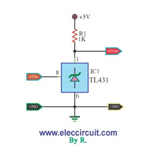
This is a simple pressure level check circuit, utilizing the integrated circuit TL431. It operates with a power supply of 5 volts for the digital circuit. The general feeding signal is... The circuit is designed to monitor pressure levels by...
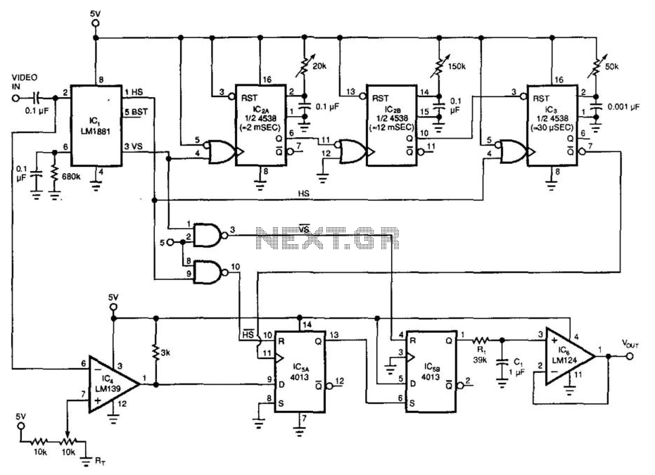
By utilizing a low-cost RS-170 camera and this circuit, a voltage that indicates the position of an object within the camera's field of view is generated. IC2A and IC2B create a valid video gate that keeps IC3 in a...
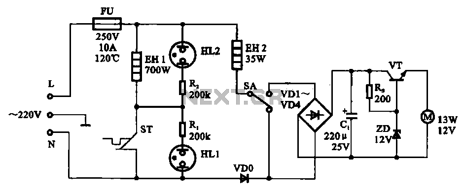
The electric thermos temperature detection control circuit is designed to monitor and manage the temperature within an electric thermos. It primarily consists of a control circuit for the boiler heater and heater insulation, an electrical magnetic pump motor drive...

A diode is utilized in a temperature sensor application circuit. Silicon diodes VD1 and VD2 serve as the temperature sensors, exhibiting a temperature coefficient of silicon diodes. The circuit includes a constant current source, VT1, which provides a steady...
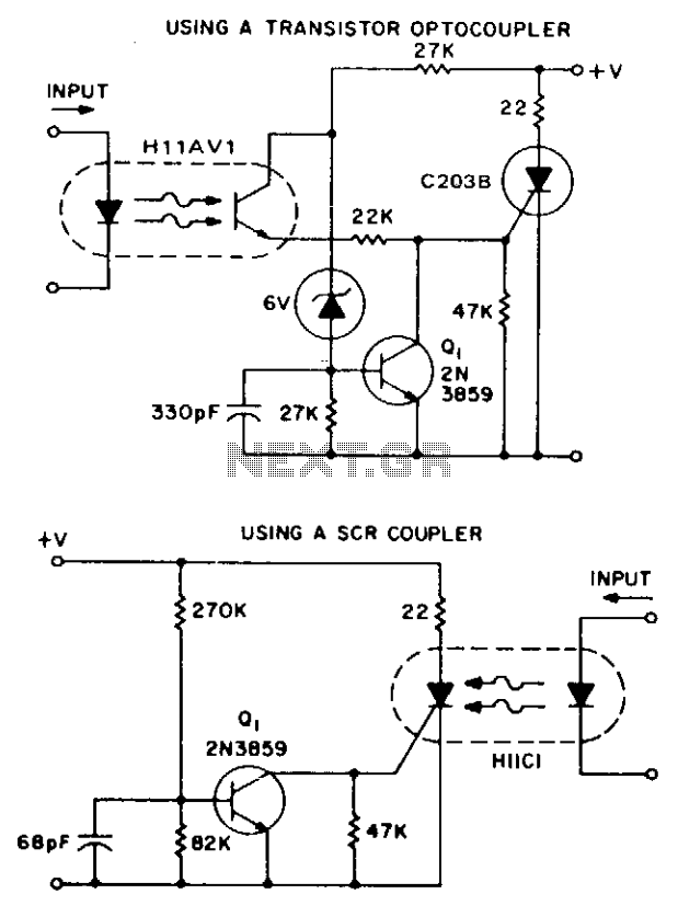
These two simple circuits provide zero voltage switching. They can be used with full wave bridges or in antiparallel to provide full wave control and are normally used to trigger power thyristors. If an input signal is present during...
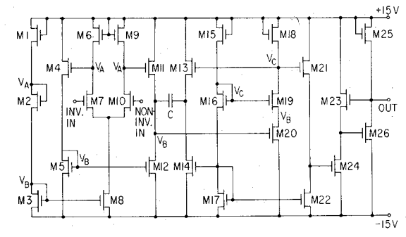
An internally compensated operational amplifier has been fabricated using n-channel Al-gate MOS technology, utilizing only enhancement mode devices. The circuit is designed to ensure that its performance remains insensitive to process parameters. The input stage consists of a source-coupled...