
10 LED VU meter LM3915

The LED VU meter circuit utilizes the LM3915 or LM3916 integrated circuit, which is designed for driving LED displays in either bar graph or dot mode. The primary function of this circuit is to visually represent audio signal levels, making it an effective tool for monitoring sound levels in various applications.
The circuit configuration includes a resistor (R1) of 1 kOhm, which is typically used for current limiting to protect the LEDs from excessive current. A capacitor (C1) with a value of 2.2 µF is included in the circuit to filter the input signal and stabilize the voltage levels, ensuring accurate representation of the audio signal.
The input audio signal is fed into pin 5 of the LM3915/LM3916 IC (referred to as IC1), where it is processed to drive the LEDs (D2 to D11). The LEDs are arranged in a sequential manner to indicate different levels of the audio signal. The design allows for up to 10 LEDs to be driven, providing a clear visual representation of the signal strength.
The display mode of the circuit can be adjusted using pin 9 of IC1. In the default configuration, the circuit operates in dot mode, illuminating one LED at a time corresponding to the input signal level. This mode is advantageous for low power consumption. By connecting pin 9 to pin 3, the circuit switches to bar mode, where multiple LEDs can be illuminated simultaneously to provide a more comprehensive visual indication of the audio level.
The simplicity of the circuit, combined with its effectiveness in visualizing audio signals, makes it suitable for various applications, including audio equipment, mixers, and sound level monitoring systems. The use of the LM3915/LM3916 IC ensures reliable performance and ease of integration into existing systems.This simple LED VU meter has only a few parts but is useful as an indicator for the noise. The circuit is built around an LM3915, the brother of the logarithmic LM3914. The input signal from the VU meter is put on pin 5 of IC1. Through pin 9 of IC1 is the display mode sets (beam or point instructions). In the drawn state IC1 works in the dot mode (point). When pin 9 is coupled to pin 3, the IC works in bar mode (beam). Obviously the whole circuit consumes less power in dot mode. Parts List R1 = 1 kOhm C1 = 2.2 uF D2-D11 = LED IC1 = LM3915 or LM3916 🔗 External reference
Related Circuits
Here is a schematic of a rechargeable 9-LED flashlight using two Gates SLA cells and nine LEDs. It is as bright as when the single bulb was used, and lasts 3 times longer per charge. That is about 10...
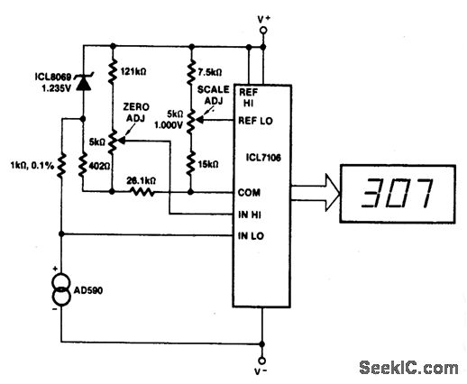
This circuit allows for zero adjustment as well as slope adjustment. The ICL8069 brings the input within the common-mode range, while the 5 K pots trim any offset at 218 °K (-55 °F) and set the scale factor. The...
The consumer unit cupboard in some older houses is poorly illuminated. If a bell transformer is also situated in this cupboard, it can be utilized to provide emergency lighting using two high-current LEDs. These diodes are powered through a...
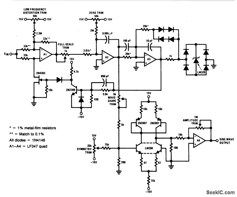
For a 0- to 10-V input, this circuit generates sine-wave outputs ranging from 1 Hz to 20 kHz, achieving linearity better than 0.2%. The distortion level is approximately 0.4%, and both the frequency and amplitude of the sine-wave output...
These small electronic lamps are quite practical and have a long lifespan. Approximately 40 years after Nick Holonyak invented the first LED, they have become nearly essential. Any dedicated electronics enthusiast typically keeps a few in their collection. Prior...
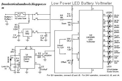
This is a low power voltmeter circuit designed for use with alternative energy systems that operate on 12V and 24V batteries. The voltmeter features an expanded scale that indicates small voltage steps within the 10 to 16 volt range...