
10 MHz FREQUENCY COUNTER

The described circuit operates as a digital counting and display system, leveraging the functionalities of three integrated circuits. The ICM7208 (U1) serves as the primary counting unit, capable of counting up to ten billion by utilizing its seven-decade architecture. It converts the counted values into a format appropriate for driving a 7-segment display, allowing for a visual representation of the counted digits.
The ICM7207A (U2) functions as an oscillator controller, generating necessary clock signals for U1. The crystal oscillator provides a stable frequency of 5.24288 MHz, which is essential for accurate timing. This frequency is divided down to 1280 Hz within U2, yielding a multiplexing signal that is critical for the operation of the display. The multiplexing signal controls the sequential illumination of the individual display segments, ensuring that only one digit is activated at a time, thus maintaining clarity and preventing ghosting effects.
The CA3130 biFET operational amplifier (U3) plays a vital role in signal conditioning. It amplifies and processes the input signals that are fed into U1, ensuring that the counting operation is not adversely affected by noise or signal degradation. This amplification is crucial for maintaining the integrity of the input signals, particularly in environments where electrical noise may be present.
Overall, this circuit is designed to provide a reliable and accurate digital counting solution, suitable for various applications where visual feedback of numerical values is required. The combination of the counter, oscillator, and operational amplifier ensures efficient operation and high performance in counting and display tasks.The circuit consists of ICM7208 seven-decade counter U1, ICM7207A oscillator controller U2, and CA3130 biFET op amp U3. IC UI counts input signals, decodes them to 7-segment format, and outputs signals that are used to drive a 7-digit display.
IC U2 provides the timing for U1, while U3 conditions the input to U1. The The circuit consists of ICM720 8 seven-decade counter U1, ICM7207A oscillator controller U2, and CA3130 biFET op amp U3. IC U1counts input signals, decodes them to 7-segment format, and outputs signals that are used to drive a 7-digit display. IC U2 provides the timing for U1, while U3 conditions the input to U1. The 5. 24288-MHz crystal frequency is divided by U2 to produce a 1280-MHz multiplexing signal at pin 12 of U2.
That signal is input to U1 at pin 16 and used to scan the display digits in sequence. crystal frequency is divided by U2 to produce a 1280-MHz multiplexing signal at pin 12 of U2. That signal is input to U1 at pin 16 and used to scan the display digits in sequence. 🔗 External reference
Related Circuits
This circuit utilizes a synthesized sound chip from Holtek, the HT-2811, which reproduces the sound of a "ding-dong" chiming doorbell. Furthermore, the circuit incorporates a CMOS 4026 counter display driver IC to count visitors. The circuit design features the HT-2811...
The primary function of the frequency counter is to measure the frequency and cycle of a signal. Its applications span a wide range, extending beyond simple instrument measurements to areas such as education, scientific research, high-precision instrument measurement, and...
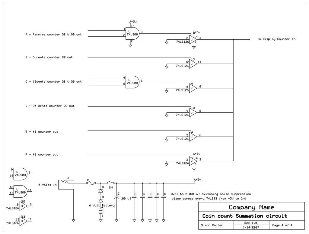
The outputs of all coin counters are summed in a 74LS126 tri-state buffer, which is used to connect all the counter outputs to the input. The circuit utilizes a 74LS126, a quad buffer/driver with three-state outputs, to manage the outputs...
Spikes in the center of a sawtooth wave are eliminated in this circuit by triggering at specific intervals. This circuit is designed to mitigate unwanted spikes that occur in the center of a sawtooth waveform. The sawtooth wave, characterized by...
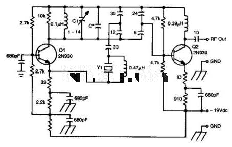
This oscillator circuit utilizes a 5th overtone crystal operating within the 85 to 106 MHz frequency range. The component Y1 represents the crystal. The circuit was initially designed for frequency control in a microwave oscillator. The oscillator circuit leveraging a...
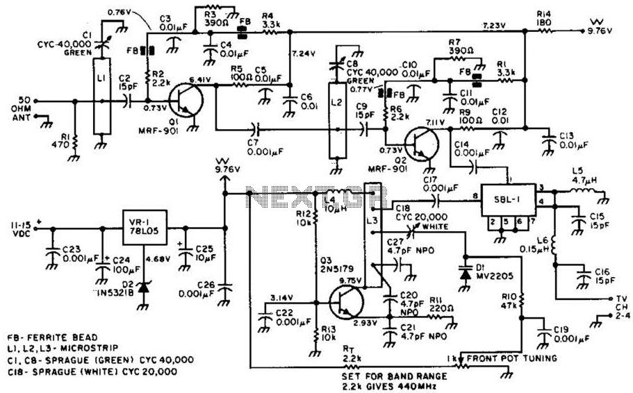
Most ATV (Amateur Television) transmitters operate using a Double Sideband (DSB) signal, while commercial television stations utilize a Vestigial Sideband (VSB) signal. This distinction is leveraged in this converter to utilize the lower sideband, thereby reducing interference from repeaters...