
100Mhz Overtone Oscillator

The oscillator circuit leveraging a 5th overtone crystal operates by utilizing the crystal's natural resonant frequency to generate stable oscillations. The 5th overtone refers to the fifth harmonic of the fundamental frequency, which provides improved frequency stability and selectivity compared to lower overtone crystals.
In this design, the crystal (Y1) is connected within a feedback loop that allows it to sustain oscillations at its resonant frequency. The circuit typically includes active components such as transistors or operational amplifiers, which amplify the oscillations generated by the crystal. Additional passive components like resistors and capacitors are used to shape the frequency response and stabilize the circuit.
The oscillator circuit's application in microwave frequency control is significant, as it ensures precise frequency generation necessary for various microwave devices, including RF transmitters and receivers. The stability provided by the 5th overtone crystal is critical in maintaining performance standards in communication systems and other electronic applications where frequency accuracy is paramount.
The design may also incorporate tuning elements to allow slight adjustments to the output frequency, accommodating for variations in component tolerances or environmental factors. Overall, this oscillator circuit exemplifies the integration of crystal technology in high-frequency applications, ensuring reliable operation within the specified frequency range. This oscillator circuit uses a 5th overtone crystal in the 85-to-106 MHz range. Y1 is the crystal. The circuit was originally used to frequency control a microwave oscillator.
Related Circuits

This circuit utilizes a single potentiometer to control a frequency range from 300 Hz to 3000 Hz. A FET operational amplifier is employed at stages A1 and A2. The upper frequency limit is dictated by the gain-bandwidth product of...
A capacitor in series with the crystal may be utilized to adjust the oscillator output frequency. The value may range between 20 pF and 0.01 µF, or it may be a trimmer capacitor, and it will approximately equal the...
The circuit utilizes standard components, produces a good sine wave, and exhibits a degree of immunity to the specific operational amplifier it is designed around. However, it can be easily misunderstood, and oversimplifications regarding its operation may lead designers...
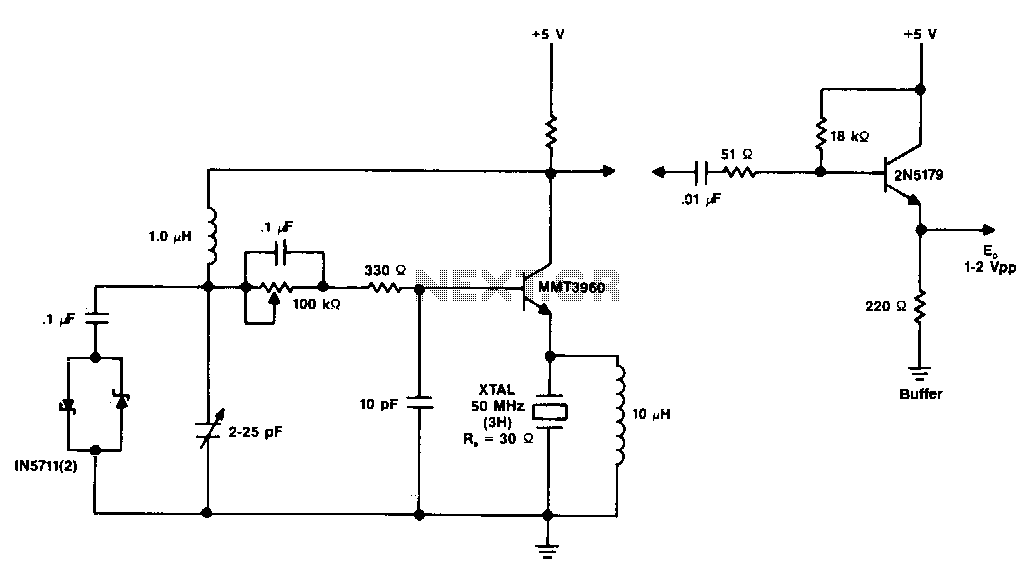
The diagram illustrates a 50 MHz oscillator functioning at its third harmonic. The collector load resistor R1 has been increased due to the rise in the quartz crystal's internal series resistance Rs, which escalates with frequency in the VHF...
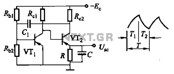
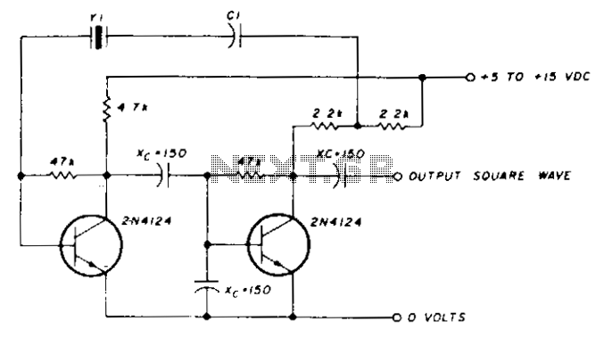
Common non-sinusoidal oscillator circuit, waveform and frequency formula - sawtooth oscillator - use multivibrator. The sawtooth oscillator is a type of non-sinusoidal waveform generator that produces a triangular or sawtooth-shaped output signal. This oscillator is commonly utilized in various applications,...
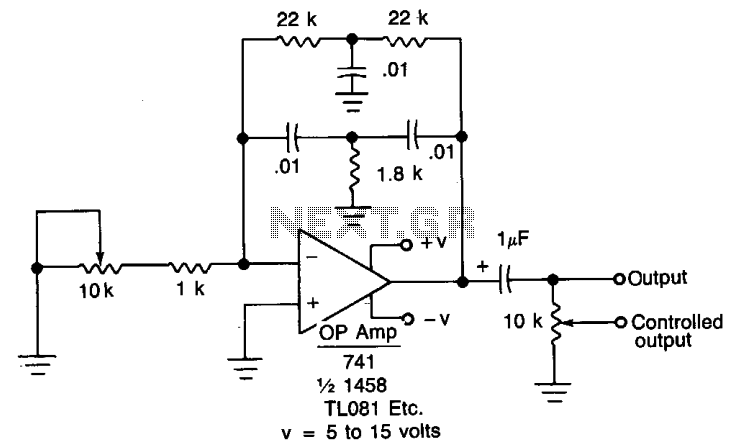
When the oscillator is connected to a DC circuit, a DC blocking capacitor should be connected in series with the potentiometer's wiper arm. For finer output control, a 10 kΩ potentiometer can be added. In this circuit configuration, the oscillator...