
Coin Counter summing the counter outputs

The circuit utilizes a 74LS126, a quad buffer/driver with three-state outputs, to manage the outputs from multiple coin counters. Each coin counter generates a digital signal representing the count of coins detected. These outputs are fed into the 74LS126, which provides a means to consolidate these signals into a single output line while maintaining signal integrity.
In operation, the 74LS126 can be enabled or disabled using its control pins, allowing for selective output from the coin counters. When enabled, the buffer will output the summed signals from the coin counters, effectively allowing the system to read the total count from a single output line. The tri-state feature of the 74LS126 is crucial in preventing signal conflicts when multiple counters are active, as only one buffer can drive the output at any given time.
This configuration is beneficial in applications where multiple inputs need to be monitored or processed without interference. The use of a tri-state buffer not only simplifies the wiring but also enhances the overall reliability of the circuit by ensuring that only valid signals are presented to the subsequent processing stage. The 74LS126 is well-suited for this application due to its fast switching speeds and low power consumption, making it an ideal choice for coin counting systems in electronic devices.The outputs of all coin counters are summed in a 74LS126 tri-state buffer which is used so that all the counter outputs can be connected to the input.. 🔗 External reference
Related Circuits
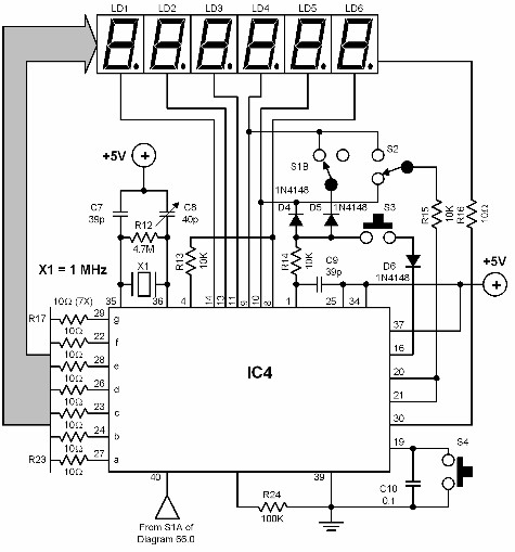
A digital audio frequency (AF) counter can be constructed using a minimal number of components by employing a single 7226B integrated circuit (IC) from Intensil, as depicted in the accompanying diagram. This circuit has an upper frequency limit of...
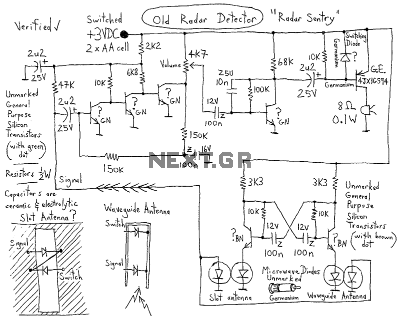
After receiving a Micro Scalextric set for Christmas and acquiring a large quantity of second-hand track from eBay, a lap counter was deemed necessary for racing against the clock and opponents. The objective was to accurately time laps, rather...
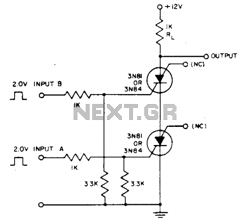
Voltage across resistor Rl is only present when inputs A and (2- to 3-V amplitude) occur simultaneously. A brief overlap of less than 1 microsecond is enough to trigger the silicon-controlled switch (SCS). Coincidence of negative inputs is detected...
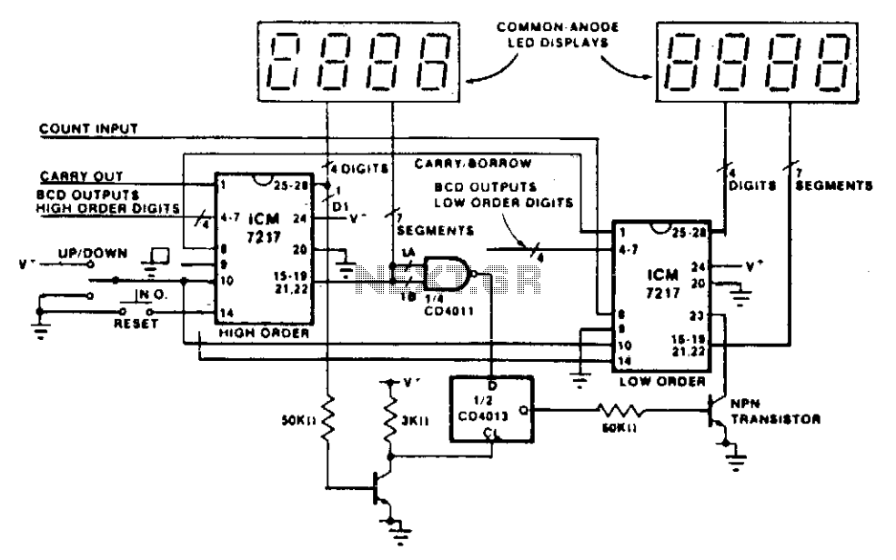
This circuit illustrates the method of cascading counters while maintaining the appropriate leading zero blanking. A NAND gate is employed to determine if a digit is active, as indicated by the activation of either segment a or b on...
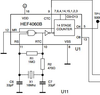
The initial issue pertains to the 16 MHz crystal oscillator, which fails to initiate oscillation. However, when substituting the 16 MHz crystal with an 11 MHz or lower frequency crystal, the oscillator functions correctly. An oscilloscope reveals a clear...
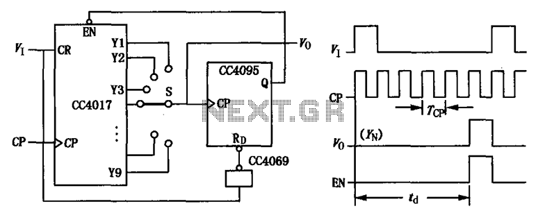
CC4017 counter/distributor featuring a circuit diagram of the delay. The CC4017 is a decade counter and distributor that counts from 0 to 10, providing ten output states. It is commonly used in various digital applications for counting purposes, such as...