
simple garage stop light circuit

The circuit utilizes six solar cells arranged to optimize light absorption and power generation. When exposed to sufficient light from the car's headlights, the solar cells generate a voltage that powers the circuit. The potentiometer P1 allows for fine-tuning the sensitivity of the light detection, enabling the user to adjust the distance at which the circuit activates based on ambient light conditions.
The relaxation oscillator N1 is designed to produce a periodic output, which is then used to drive the flashing LED D3, providing a visual indication of successful activation. The choice of the BC547B transistor allows for reliable switching with low power consumption, making the circuit efficient. The inclusion of diodes D1 and D2 not only stabilizes the circuit but also provides a buffer against voltage fluctuations, ensuring consistent operation.
The design of the circuit on a veroboard allows for easy assembly and modifications if necessary. The use of a translucent or transparent case not only protects the components but also facilitates light entry to the solar cells, ensuring they remain functional. Proper positioning of the assembly is crucial; it must be installed in a way that maximizes exposure to the car's headlights while ensuring the LED is easily visible to the driver, enhancing user experience during parking.
Overall, this innovative approach to using solar cells for car positioning not only improves practicality but also promotes energy efficiency by utilizing renewable energy sources.A novel use of solar cells makes positioning your car in the garage rather easier than old tyres, a mirror, or a chalk mark. The six solar cells in figure 1 serve as power supply and as proximity sensor. They are commercially available at relative low cost. The voltage developed across potentiometer Pi is mainly dependent on the intensity of the l ight falling onto the cells. The circuit is only actuated when the main beam of one of the car`s headlights shines direct onto the cells from a distance of about 200 mm (8 inches). The distance can be varied somewhat with P, Under those conditions, the voltage developed across C1 is about 3 V, which is sufficient to trigger relaxation oscillator Ni.
The BC547B is then switched on via buffer N2 so that D3 begins to lfash. Diodes Di and D2 provide an additional in- crease in the threshold of the circuit. The total voltage drop of 1. 2 V across them ensures that the potential at pin I of the 4093 is always 1. 2 V below the voltage developed by the solar cells. As the trip level of Ni lies at about 50 per cent of the supply voltage, the oscillator will only start when the supply voltage is higher than 2. 4 V. The circuit, including the solar cells, is best constructed on a small veroboard as shown in figure 3, and then fitted in a translucent or transparent man- made fibre case.
The case is fitted onto the garage wall in a position where one of the car`s headlights shines direct onto it. The LED is fitted onto the same wall, but a little higher so that it is in easy view of the driver of the car.
When you drive into the garage, you must, of course, remember to switch on the main beam of your headlights! 🔗 External reference
Related Circuits

This circuit design for an amplifier was created to address the gap in the 3-10 Watts power output range of audio amplifiers available in RED Free Circuit Designs. A straightforward, low-component-count amplifier was developed based on the successful 45...

This receiver, designed around the popular ZN414 integrated circuit, operates within the AM band frequency range of 550 to 1600 KHz. For Longwave reception, it is necessary to replace the coil, which can be sourced from an old medium...
A circuit is being designed to operate based on car locks, which receive a negative pulse to activate a latched relay, powering the ACC line that connects to a startup/shutdown controller. The current circuit configuration presents a challenge; to...
The growth in the number of LCD segments increases the pin count required for the LCD driver package. An LCD driver IC with a key-scan function alleviates the workload on the microprocessor. However, this increase in pin count complicates...
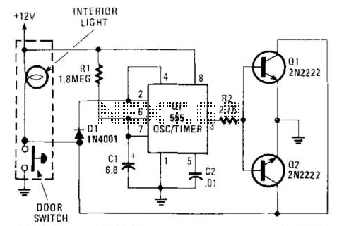
When the door is closed, this circuit maintains the dome light illumination for a duration determined by the values of R1 and C1. The approximate time is given by the equation (1.1)R1 x C1. The described circuit functions as a...
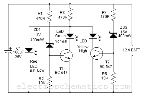
This is a simple battery monitor circuit designed for a quick assessment of a 12-volt lead-acid battery. Continuous monitoring of battery charge is essential to extend its lifespan. The battery monitor circuit typically consists of a voltage divider, an operational...