
Power Amplifier Speaker Protection Circuit Schematic

The power amplifier speaker protection circuit is designed to prevent loud thump sounds during the power-up sequence of an amplifier, which can potentially damage speakers. This circuit typically employs a relay-based design that disconnects the speakers from the amplifier output during the initial power-up phase.
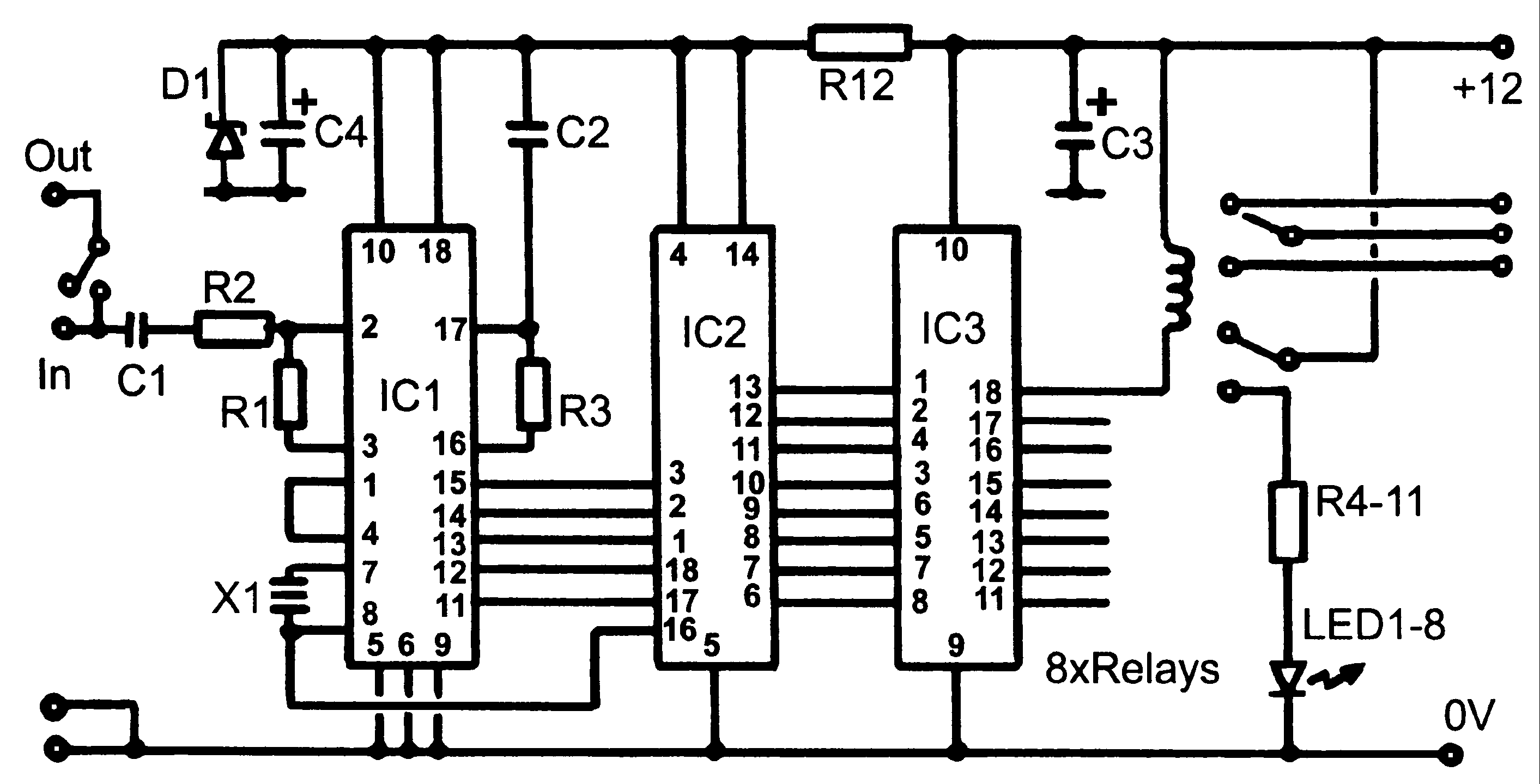
The schematic generally includes the following components: a relay, which acts as a switch to connect or disconnect the speakers; a delay timer circuit, which ensures that the relay remains open for a brief period after the amplifier is powered on; and a protection diode that prevents back EMF from the relay coil from damaging other components in the circuit.
Upon powering the amplifier, the delay timer circuit is activated, allowing a short time for the amplifier to stabilize. During this period, the relay remains in the open position, isolating the speakers from the output. Once the timer completes its cycle, the relay is energized, closing the circuit and connecting the speakers to the amplifier output. This sequence effectively eliminates the loud thump sound, providing a safer operation for both the amplifier and the connected speakers.
The use of high-quality components is essential to ensure reliability and performance. Additionally, the circuit may incorporate indicator LEDs to show the status of the relay operation, enhancing user feedback. Overall, this protection circuit is a crucial addition to any power amplifier design, safeguarding against potential audio transients that could harm speaker systems.Power Amplifier Speaker Protection Circuit Schematic While switching a power amplifier on, a loud thump sound is heard to sudden heavy discharge.. 🔗 External reference
Related Circuits
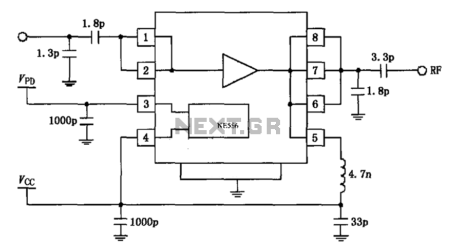
The circuit depicted in the figure is based on the RF2126, a 2450 MHz end-stage linear power amplifier. The radio frequency (RF) signal enters through input pin 1 and is subsequently amplified by the amplifier stages (pins 5, 6,...

The device is referred to as the Itsy Bitsy USB Lamp. This concept is remarkably straightforward, raising the question of why it had not been conceived earlier. Originating as a student project at Massey University in Wellington, New Zealand,...
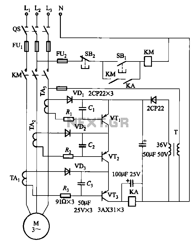
Drawing transistors that comprise the gate VTi, VT2, VT3, and similar components. The schematic involves a configuration of transistors designated as VTi, VT2, and VT3, which are integral to forming a gate structure. These transistors are typically arranged in a...
This is a replacement power source for 1.3V mercury cells or other small batteries. It has many uses and I use this circuit in my computer to power a front panel multi adapter which has a digital thermometer. This...
This project has two options. It can be a mains operated project, using a 2155 or 2156 transformer or it can be connected to a plug pack. We recommend it be connected to a 16v AC 1 amp plug...
Control monitoring equipment at a TV repeater site is designed to accept commands sent as DTMF tones over the repeater's audio channel. It is capable of switching either AV signals or power supply feeds with currents up to 1...