
10 W Audio Amplifier

The described audio amplifier circuit serves as a versatile solution for applications requiring moderate audio power amplification. The primary components, 2N3055 and MJE2055, are robust power transistors well-suited for handling significant output currents and voltages, making them ideal for audio amplification tasks.
The circuit's design typically includes a power supply stage that provides the necessary voltage levels for the transistors to operate efficiently. The 2N3055 transistor functions as the main output device, capable of delivering substantial power to the load, while the MJE2055 can be used for driving the output stage or as a complementary push-pull configuration to enhance performance and reduce distortion.
Biasing is critical in this circuit to ensure that the transistors operate in their optimal range. By adjusting the bias resistors, the quiescent current can be set appropriately, which affects the linearity and efficiency of the amplifier. Higher voltage operation can be achieved by selecting a suitable power supply, allowing for increased output power while maintaining sound quality.
The circuit may also incorporate additional components such as capacitors for coupling and decoupling, resistors for feedback and stability, and possibly a heat sink for thermal management of the output transistors. Overall, this audio amplifier circuit is designed to provide reliable performance in various audio applications, making it a valuable tool for both amateur and professional audio engineers.This circuit is a general-purpose 10-W audio amplifier for moderate-power PA or modulator use in an AM transmitter. With higher voltages and a change in bias resistors, up to 30 W can be obtained. The Output Stage Amplifier using transistor 2N3055 and MJE2055. 🔗 External reference
Related Circuits
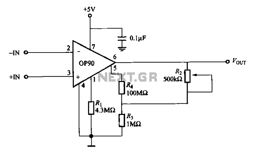
Compared to other operational amplifiers, the OP90 has a significant advantage in low power consumption. Its low power requirements allow for a wide range of power supply voltages (from 1.6V to 18V, and it can also operate with dual...
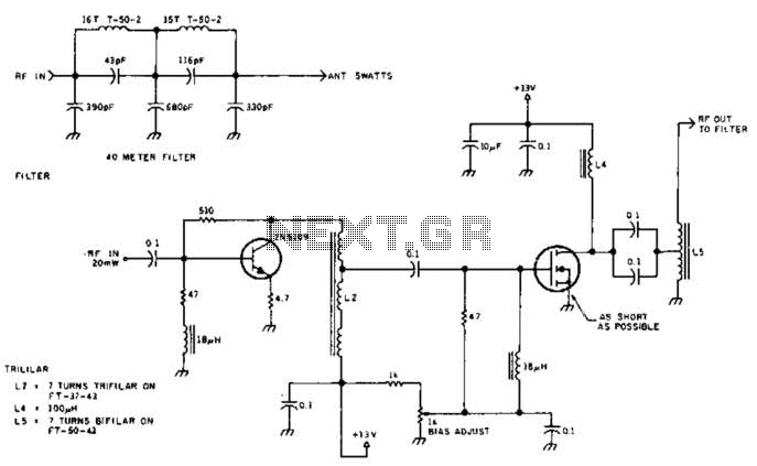
The circuit illustrated is designed to generate up to 5 watts of RF output in the 40-meter (7 MHz) amateur band. The coils depicted are wound on toroidal cores from Armdon Associates Inc., with part numbers provided in the...
The LMC568 is an amplitude-linear phase-locked loop that includes a linear voltage-controlled oscillator (VCO), fully balanced phase detectors, and a carrier detect output. It utilizes LMCMOS technology to achieve high performance while maintaining low power consumption. The VCO features...
Both transistors should be low noise types. In the original circuit, BC650C was used, which is an ultra-low noise device. These transistors are now hard to find, but BC549C or BC109C are good replacements. The circuit is self-biasing and...

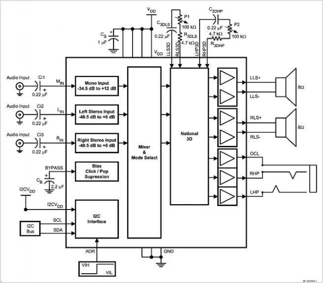
This circuit combines two or more audio channels into a single channel (for example, converting stereo to mono). It is capable of mixing multiple channels while consuming minimal power. The schematic illustrates two inputs, but additional inputs can be...
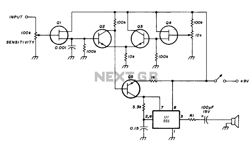
The transistor Q5 and the 1000-ohm resistor form the variable element necessary for controlling the frequency of the voltage-controlled oscillator (VCO) by limiting the charging current flowing into the 0.15 microfarad timing capacitor based on the forward bias applied...