
Four reversing operation of the reverse brake circuit

The circuit operates by employing a relay as a primary switching mechanism, which enhances its reliability in adverse environmental conditions such as dust and moisture. The relay is activated by a control signal that dictates the operational state of the connected load, which can include motors or other devices requiring speed regulation.
Key components of the circuit include the relay itself, which is rated for the specific voltage and current required by the load. The relay contacts are designed to handle the electrical load while minimizing wear and tear, thus extending the operational life of the circuit. The circuit may also incorporate protective devices such as fuses or circuit breakers to prevent damage from overload conditions.
In addition to the relay, the circuit may feature capacitors and resistors to filter noise and stabilize the control signal, ensuring smooth operation under varying load conditions. The design may also include indicators such as LEDs to provide visual feedback on the operational status of the relay.
Overall, this circuit is optimized for durability and reliability, making it suitable for applications in industries where equipment is exposed to harsh environmental factors. Proper installation and maintenance are essential to ensure the longevity and effectiveness of the circuit in real-world applications. Circuit shown in Figure 3-131. It uses a relay in place of the speed control relay. The circuit is suitable for dusty rings and other poor environmental situation.
Related Circuits
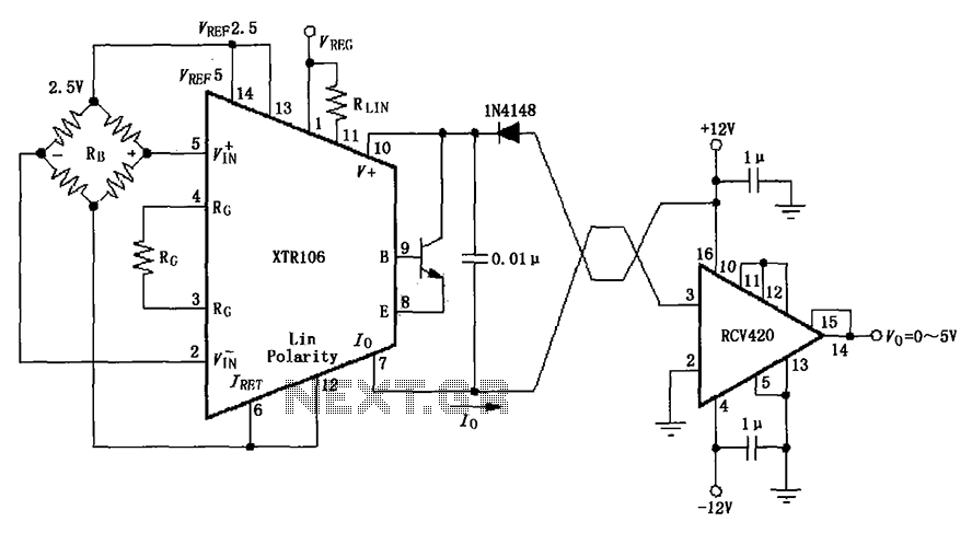
The IN4148 series diode is connected in the V+ line and configured in a loop to prevent damage from reverse voltage conditions. The diode exhibits a forward voltage drop of approximately 0.7V, which affects the supply voltage. The circuit...
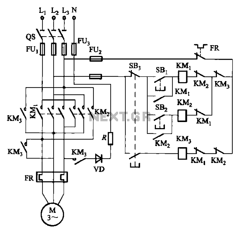
The circuit illustrated in Figure 3-145 employs a rectifier diode brake for neutral grounding in a three-phase, four-wire power supply system. This circuit design incorporates a rectifier diode brake, which plays a crucial role in ensuring the safety and reliability of...

This simple tone control (bass and treble control) can be utilized in various audio applications. It can be integrated into amplifiers, function as a standalone control module, or even be incorporated into new and innovative instruments. The circuit employs...
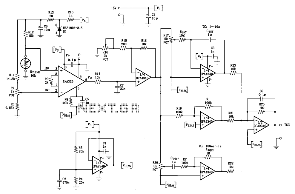
The INA326/327 forms a single power PID (proportional-integral-derivative) controller as illustrated in the temperature control loop. This circuit is primarily designed for temperature measurement and control. A thermistor, designated as RTHERM, detects temperature changes and converts them into an...
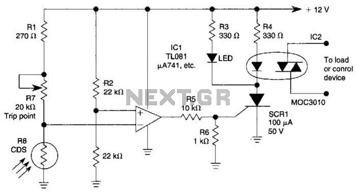
The light-sensitive CDS cell R8 is configured in a bridge circuit with IC1 functioning as a comparator. When light strikes the CDS cell R8, the output of IC1 goes high, triggering SCR1. This action illuminates LED1 and activates opto...
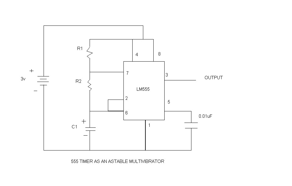
An astable multivibrator, commonly referred to as a free-running multivibrator, is a circuit that generates rectangular waves without the need for external triggering. The timing characteristics of this circuit are determined by the values of the resistors and capacitors...