
Simple FM Transmitter Circuit (88-108MHz) With 2N2222 Transistor
 With 2N2222 Transistor")
This simple transmitter circuit is designed to provide reliable performance within the specified voltage range. It typically consists of key components such as a transistor, an oscillator circuit, and an antenna. The circuit is powered by a DC power supply ranging from 9 to 12 volts, making it suitable for various applications where moderate transmission distances are required.
The core of the transmitter is often based on a common emitter or common base configuration, utilizing a bipolar junction transistor (BJT) or a field-effect transistor (FET) to amplify the radio frequency (RF) signal generated by the oscillator. The oscillator may be constructed using a combination of resistors, capacitors, and inductors to establish the desired frequency of operation. The frequency can be adjusted by varying the capacitance or inductance in the circuit, allowing for tuning to specific channels or frequencies.
The antenna connected to the transmitter is crucial for effective signal transmission. Depending on the application, different types of antennas can be used, such as dipole, monopole, or loop antennas, each offering varying characteristics in terms of gain and radiation pattern.
To ensure optimal performance, the circuit should be designed with attention to component selection, layout, and grounding techniques to minimize interference and enhance signal clarity. Proper shielding may also be employed to protect the circuit from external noise sources, thereby improving the overall transmission quality.
In summary, this simple transmitter circuit diagram serves as a foundational design for various RF transmission applications, providing essential features such as tunability and decent coverage, while operating efficiently within the specified voltage range.This is simple transmitter circuit diagram which has some what good coverage. This circuit can be operated with 9-12V power supply. To tune this .. 🔗 External reference
Related Circuits
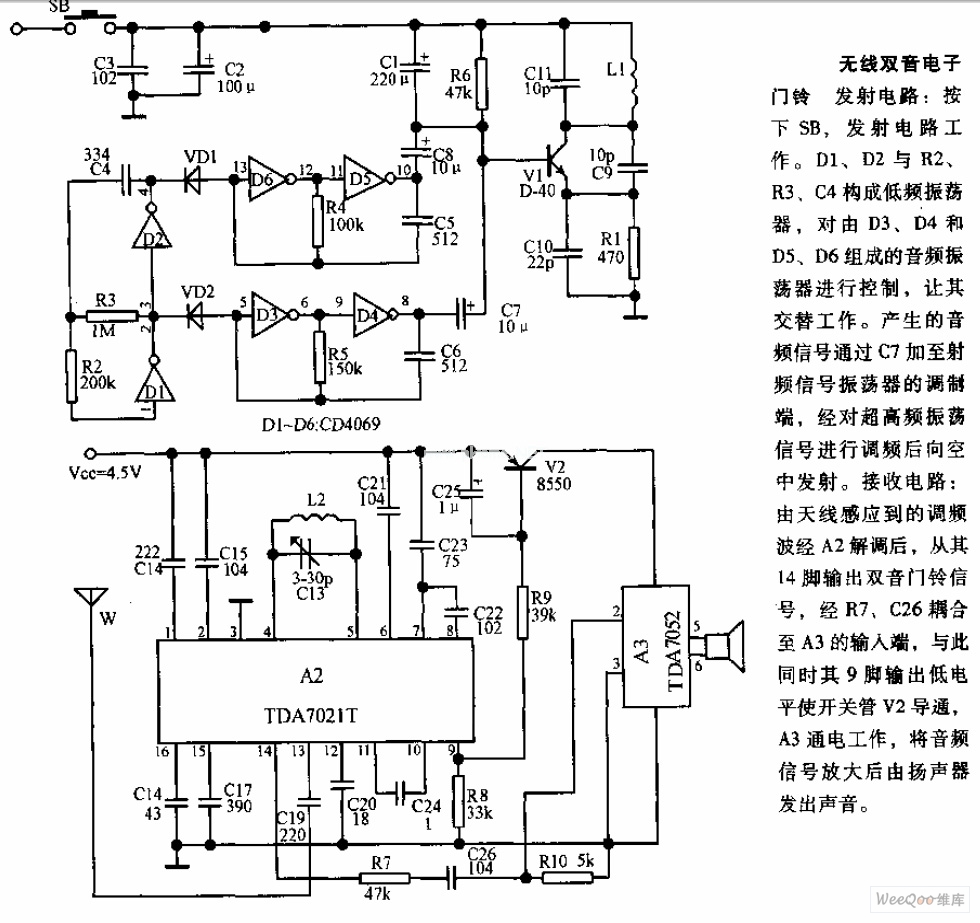
The transmitter circuit is activated by pressing the SB button. Components D1, D2, R2, R3, and C4 form a low-frequency oscillator that controls an audio oscillator made up of D3, D4, D5, and D6, allowing them to operate alternately....

Due to the varying conditions of different input signals, when an abnormal voltage is applied to the pin, protection circuits are designed to create a circuit path that secures the internal protection of large-scale integration (LSI) circuits. The structure...
This circuit differs from similar circuits in view of its simplicity and a totally different concept of generating the control signals. Usually remote control circuits make use of infrared light to transmit control signals. Their use is thus limited...
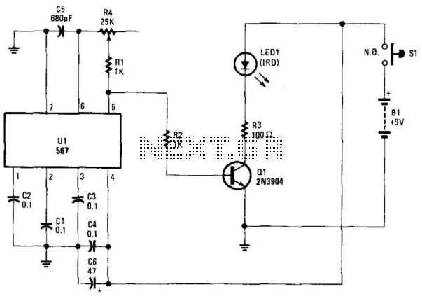
Using an NE567 as a tone oscillator, this circuit produces an infrared (IR) signal from the LED, which is modulated with a square wave. LED1 is an IR-emitting LED. The modulation enhances performance under high ambient light conditions. The circuit...

A VOX is a voice-operated switch that is often used as a substitute for the press-to-talk switch on a microphone. This VOX can be connected to almost any audio equipment that has a socket for an external loudspeaker. The...

A stable and straightforward FM transmitter circuit is presented here. With a properly matched antenna, this transmitter can achieve a range of approximately 200 meters. The circuit utilizes a condenser microphone (K1) to capture the sound intended for transmission....