
100 MHz RF oscillator with ATtiny12

The described circuit utilizes a Saronix crystal oscillator as a frequency reference for an RS-232 to 100 MHz RF desktop channel adapter. The oscillator's output is configured with an open emitter configuration, which allows for a straightforward method of modulation and signal generation. The circuit employs an Atmel ATtiny12 microcontroller, which is programmed to generate a square wave signal. This microcontroller is a compact and efficient solution, requiring fewer components than traditional timer circuits like the NE-555.
In this setup, a 330 Ohm load resistor is connected to the output of the oscillator. When this resistor is grounded, it enhances the RF output, making it more suitable for RF applications. Modulation control is managed by a transistor, specifically the MPSH34, which is used to switch the load resistor on and off. This gating mechanism allows for dynamic control over the oscillator's output.
The circuit also features a Single Pole Double Throw (SPDT) switch that provides flexibility in modulation input. In one position, the switch connects the square wave output from the ATtiny12 to the base of the MPSH34, enabling the generation of modulated signals. In the alternate position, an external modulation source can be applied. If no external modulation is connected, the circuit defaults to maximum RF output due to the presence of two 10K pull-up resistors connected to the transistor's base, ensuring that the MPSH34 remains in an 'on' state.
This design approach is particularly advantageous for applications requiring a compact and efficient modulation scheme, and it can be adapted to work with other oscillators that necessitate an external pull-down resistor on their outputs. The overall configuration emphasizes simplicity and functionality, making it a practical solution for RF signal generation and modulation in various electronic projects.A frequency reference for tuning up the RS-232 to 100 MHz RF desktop channel adapter elsewhere on this site, when I found this Saronix crystal oscillator in my junk box. A few minutes with AVRStudio produced an ATtiny12 to make a tone - even fewer parts than using an NE-555.
With the addition of a transistor to gate the output, I was set to go. Quick and dirty, but it was useful. The Saronix oscillator has an open emitter output. When the 330 Ohm load resistor on the output is grounded, the RF out of the oscillator increases. Modulation is affected by driving the MPSH34 on and off to switch the 330 Ohm load resistor. An Atmel ATtiny12 provides a square wave signal that can be used to drive the MPSH34, or if the SPDT switch is in the other position, an external modulation source can be used to modulate the signal, or if nothing is connected to the modulation input, the RF output is at maximum value because of the two 10K pull-up resistors on the base of the MPSH34. This technique should work with an oscillator that requires an external pull-down resistor on its output.
🔗 External reference
Related Circuits

The RF engineer often needs an instrument that can reliably and quickly check a low-frequency quartz crystal unit. However, such equipment is challenging to find, and engineers frequently refer to electronic circuit handbooks for schematics that can perform this...
The Bong circuit is a high-frequency Colpitts oscillator that utilizes a Ge coil (L). It features two heads and is designed for simple production. The frequency of oscillation can be determined, and testing is conducted to ascertain the value...

This free-running square-wave oscillator utilizes two NPN transistors. The output frequency is approximately 300 Hz with the specified component values. The circuit operates as a basic oscillator, generating a square wave output through the interaction of two NPN transistors. The...

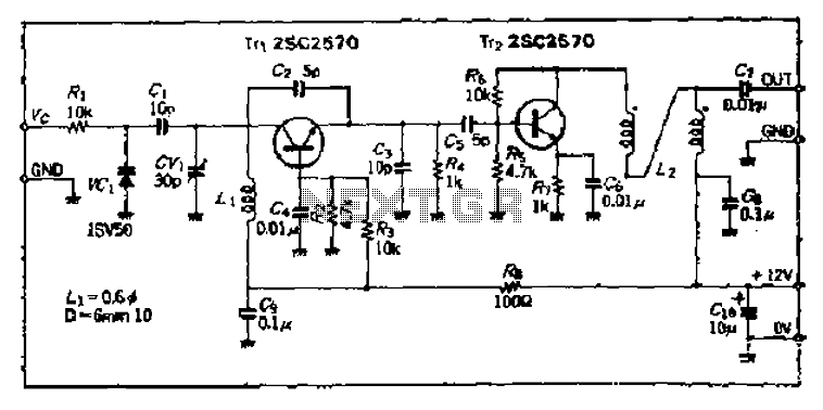
The only adjustments that require close attention are input, output, and neutralization. The 150-pF capacitor in the input line compensates for impedance mismatch. The tuning process is aimed at achieving maximum signal transfer from the exciter to the final...

In this circuit, U1 is a frequency converter that supplies the 455-kHz intermediate frequency (IF) stage U2 and detector U3. U4 serves as the audio output stage. R9 functions as a gain control, allowing for the adjustment of the...
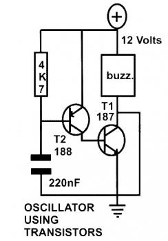
This schematic diagram represents a basic oscillator circuit utilizing two transistors. When the transistors and several passive components are connected as illustrated, the circuit begins to oscillate. The oscillation frequency can be modified by altering the values of either...