
100W Class-A//AB Amplifier

The original simple 1969 JLH class-A design provided excellent first cycle accuracy through mid and high frequencies (dynamic clarity) because there were no stabilisation components nor a series output choke, whilst the NFB error correction was established via the input emitter (some describe this as current feedback). However, it did generate rather a lot of heat, the damping was soft at lower frequencies and the positive slew was weaker in the presence of loudspeaker system generated back-EMF at higher audio frequencies.
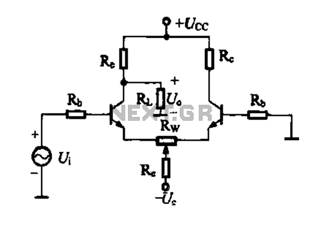
The Class A/Class AB amplifier circuit operates by utilizing a complementary push-pull configuration, which allows for efficient power delivery while minimizing distortion. The design typically incorporates bipolar junction transistors (BJTs) or metal-oxide-semiconductor field-effect transistors (MOSFETs) in the output stage, with the goal of achieving high linearity and low crossover distortion.
The circuit features a biasing network that ensures the transistors operate in Class A mode at lower signal levels, providing high fidelity and minimal signal distortion. As the input signal increases, the amplifier transitions into Class AB operation, allowing for greater efficiency and reduced heat generation during high power output scenarios.
Key components include the input stage, which may consist of a differential amplifier configuration to improve common-mode rejection and enhance signal integrity. Feedback is applied from the output to the input stage, often using a negative feedback loop to maintain linearity and control gain. The absence of stabilizing components in the original design contributed to its dynamic clarity, but modern iterations may incorporate additional elements to improve thermal stability and frequency response.
Thermal management is critical in this design, as Class A operation can lead to significant heat generation. Heat sinks are typically employed to dissipate excess heat, and thermal protection circuits may be included to prevent damage from overheating. Additionally, the design may utilize output capacitors to block DC offset and protect the loudspeakers from potential damage.
Overall, this amplifier design balances the benefits of Class A's audio fidelity with the efficiency of Class AB operation, making it suitable for high-performance audio applications while addressing previous limitations such as heat generation and frequency response.A Class A // Class AB amplifier rated 100 Watts when driving a 4 ohm loudspeaker. This circuit developed out of my 30+ years of JLH class-A based investigations. The original `simple` 1969 JLH class-A design provided excellent first cycle accuracy through mid and high frequencies (dynamic clarity) because there were no stabilisation components nor a series output choke, whilst the NFB error correction was established via the input emitter (some describe this as current feedback). However it did generate rather a lot of heat, the damping was `soft` at lower frequencies and the positive slew was weaker in the presence of loudspeaker system generated back-EMF at higher audio frequencies. I was eventually able to improve upo 🔗 External reference
Related Circuits
The circuit is very simple and incorporates darlington output transistors that will provide more than enough output current than is needed to drive a 3-ohm speaker. The gain may be pre-set for a variety of input levels, making it...
This is a small audio amplifier, similar to those used in small transistor radios. The circuit draws approximately 30 milliamps from a 9-volt supply and consists of two stages. The first stage is the input stage using a 2N3053...
A differential amplifier circuit can be connected in four different ways, allowing for a comparison of their characteristics. The gain of the amplifier is equivalent to that of a single tube, with half the gain providing a high common-mode...
Electronics Circuits Reference Archive Audio preamplifier circuits. There are thousands of preamplifier circuits. Here are three that are somewhat different and have garnered interest. Intercom preamp: A very convenient way of making an intercom system. Audio preamplifiers are essential components...
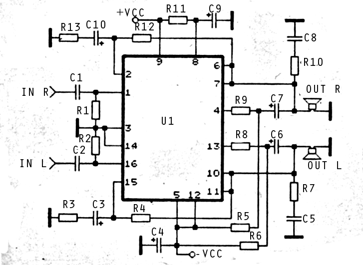
The audio amplifier circuit is highly suitable for home use, particularly with subwoofer or woofer speakers. Commonly referred to as a home amplifier, these audio amplifiers are based on integrated circuits (ICs), specifically the STK series, which includes models...
This circuit was submitted by Graham Maynard from Newtownabbey, Northern Ireland. It has an exceptionally good high frequency response, as demonstrated by applying a 100kHz squarewave to the input. Response graphs were produced using Tina Pro to highlight these...